Continue to Site

Welcome to EDAboard.com

Welcome to our site! EDAboard.com is an international Electronics Discussion Forum focused on EDA software, circuits, schematics, books, theory, papers, asic, pld, 8051, DSP, Network, RF, Analog Design, PCB, Service Manuals... and a whole lot more! To participate you need to register. Registration is free. Click here to register now.

Help analyzing this coil

Status
Not open for further replies.

mr_monster

Member level 4
Joined
May 10, 2012
Messages
79
Helped
0
Reputation
0
Reaction score
0
Trophy points
1,286
Activity points
1,964
I have an Inductor and I ran a scan form 20Hz to 20KHz on an impedance meter and got very strange results. I measured L and |Z| and for starters got very different results than my DVM which is measuring in 270Hz. The plot starts with a value of 770mH @ 20Hz and goes up to around 950mH @ 20KHz, but the higher the freq. the more the inductance changes and it is not a monotonic function as it will jump up and down (the higher the freq.).

I also observed |Z| and I can see a pretty "random" behavior, here is the 1st part of the plot. I will appreciate explanations from people who know about magnetics.
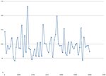
impedance.jpg
 

The |Z| plot mainly suggests an unsuitable measurement setup or broken impedance meter.

To determine L and reasonable frequency range for the measurement, you should rather a show complex impedance or magnitude/phase plot.

Before impedance and LCR meters have been become popular, people used to determine complex impedances with a generator, a reference resistor and multiple voltage measurements on pencil and paper. It's still an option.
 
The strange thing is that is measures resistors and capacitors well, however having trouble with inductance...
 

Status
Not open for further replies.

Part and Inventory Search

Welcome to EDABoard.com

Sponsor

Back
Top