Continue to Site

Welcome to EDAboard.com

Welcome to our site! EDAboard.com is an international Electronics Discussion Forum focused on EDA software, circuits, schematics, books, theory, papers, asic, pld, 8051, DSP, Network, RF, Analog Design, PCB, Service Manuals... and a whole lot more! To participate you need to register. Registration is free. Click here to register now.

(help!!)32.768kHz crystal oscillator

Status
Not open for further replies.

simao

Newbie level 4
Joined
May 10, 2006
Messages
6
Helped
0
Reputation
0
Reaction score
0
Trophy points
1,281
Activity points
1,360
32.768khz crystal inductance

hi, all
I am designing a 32.68kHz crystal oscillator now and have some problemes.
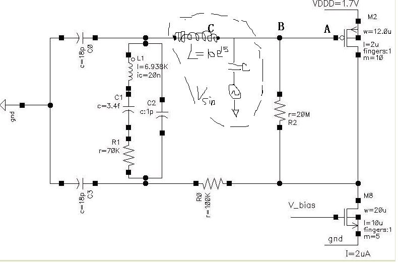
1. The quartz crystal i will use is FC135 of EPSON, in designing i need a equivalent crystal model to simulate, the parameters from datasheet of fc135 is listed below:

motional capacitance(C1):3.4fF
series resistance(R1):70Kohm max.
shunt capacitance(C0):1pF
load capacitance(CL):9pF or 12.5pF

now my question is does the motional inductance can be calculated by equation fs=1/[2*pi*(C1*L1)^0.5] ?

the L1 i calculated by this equation and value of C1=3.4fF is about 6.9KH, does this value correct? and if the value is too large?

2. I simulated the crystal oscillator by spectre and found that the circuit can't oscillate, when i give L1 a initial current as 10nA, i got a sine wave with a decreased amplitude, and when i give a 50nA initial current i got a sine wave with a increased amplitude, the question is if i simulate the circuit at a 50 nA initial current of L1 it will work correctly but when i implement the chip can it work correctly? does the initial current of the L1 have some limit?

3. The inverter i designed need about 6uA DC current to get a transconductance(gm) larger than 80uS to make it oscillator, but the specification of the supply current is no more than 3uA, is there any mearment to get a larger transconductance without increasing the dc current?

thanks very much for you attention!
 

fc-135 32.768khz a-ac

can you extend you problems in short ?

i am not getting much from explanation

thank you.
 

32.768khz inductance

hi manish

my question is:

1. can i use the parameters from datasheet of crystal to calclate motional inductance of crystal to make a equivalent model so as to use it to simulate in spectre, because the datasheet don't give the motinal inductance.

2.does a 6.9KiloHenry inductance in crystal model too large to make sense?

3.what' the difference between the 10nA and 50nA initial conditions? if i make the circuit oscillate under a 50nA initial current. does this circuit really work when implemented and connet a real crystal?

4.does a MOSFET can provide a transconductance larger than 80uS under a 3uA operation current?

attachment is the datasheet of crystal FC-135

thank you!
 

32.768khz crystal oscillator simulation

2.does a 6.9KiloHenry inductance in crystal model too large to make sense?
Yes, it has sense because it is not a physical inductance but the model parameter only.
I never used initial conditions for my simulation and never calculate Gm of invertor mosfets.
I used open loop AC analysis and sized transistor down to get AC gain for 32kHz about 2 for worst case.
After that I run simulation with conservative set and more than 2 seconds simulation time. If simulation run slowly that means oscillator already running and you should wait until it's amplitude increase upto acceptable value.

But this simulation may take a lot of time. So may be your method with initial condition will help you to speed up the simulation. But your initial condition should be very close to steady-state condition otherwise you will need wait intil you get steady-state simulation result.
 

    simao

    Points: 2
    Helpful Answer Positive Rating
32.768khz crystal schematic

hi Fom, thanks for your help!

but how can i do the open loop ac analysis, i did it like this: put a vdc source between inverter input and the crystal, and set the dc value equal to 0 and ac value equal to 1, and then run a ac simulation, finally calculate vout/vin(where vout and vin is minus and plus terminal of the vdc source respectively). then i got a bode plot and attached below, but i doubt if this method is correct, because from the bode plot i find the gain at the frequency where phase euqals to 0 is always larger than 0dB but the oscillator can't oscillate any way. If the method is not correct can you give me a method to simulate the open loop ac gain and phase.

thank you :)

Added after 10 minutes:

this is the ac gain and phase i got.
 

crystal oscillator khz sine wave

i 'm working on the same job these days, and i use nearly the same model, i already have a circuit which has taped out, there isn't a 200 res to avoid ESD instead of a 100k res between D and crystal. however, my current circuit doesn't work
 

inverter crystal 32.768khz

simao said:
hi Fom, thanks for your help!

but how can i do the open loop ac analysis, i did it like this: put a vdc source between inverter input and the crystal, and set the dc value equal to 0 and ac value equal to 1, and then run a ac simulation, finally calculate vout/vin(where vout and vin is minus and plus terminal of the vdc source respectively). then i got a bode plot and attached below, but i doubt if this method is correct, because from the bode plot i find the gain at the frequency where phase euqals to 0 is always larger than 0dB but the oscillator can't oscillate any way. If the method is not correct can you give me a method to simulate the open loop ac gain and phase.

thank you :)

Added after 10 minutes:

Oscillator simulation needs a external stimuli to spur the ckt to amplifier the noise component of resonant frequency in Spectre simulation.

this is the ac gain and phase i got.

Added after 54 seconds:

Oscillator simulation needs a external stimuli to spur the ckt to amplifier the noise component of resonant frequency in Spectre simulation.
 

32.768khz crystal oscillator cap

Hi simao!
You did everything right.
But I noticed the strange thing: why is gain for lower frequency is 0dB.
It seems your inverter operates not as an amplifier. Do you have resistor connected between invertor input - output?
Can you attach your schematic also?
 

mos crystal oscillator design freescale

hi Fom

i dont know why the gain for low frequency is 0dB, for the simulation results, the gain for low frequency even below 0dB, does this the key problem?

attachment is the scehmatic, i did have a 20 Megaohm resistor connected between inverter input and output, and the tran simulation results is aways a sine wave with a decreasing amplitude. i tried everthing i can to change but it did not work:cry:

and there is a another problems i have find, that is there is a comparator with hysterises connected between the inveter input and output, in order to shape the waveform, now i find that when i give a initial current to make the init oscillate amplitude larger than the hysterises window of the comparator, the oscillator will start up. but i think the comparator should not influence the operating of the oscillator, because the oscillator is just conneted to the gate of comparator diffrential pair. how do you think? and if i use this schem can it really work?

thx for you help agian and you are a very warmhearted man!
 

32.768khz external oscillator circuit

Schematic seems reasonable.
Where you connect the VDC source with AC=1?
What you consider to be an invertor: 2 mos including 20M resistor or only 2 mos? I mean where was your input: PMOS gate or PMOS gate and 20Mresistor?
 

32.768khz motional inductance

you shoud check the inverter circuit first . whether does it work in a amplifer condition.
I have made a oscillator circuit which is similar to yours. But the inverter circuit is not the same. I connect the gate of PMOS and NMOS, and connect the drain of them to their gates with a large resistor for biasing the inverter in amplifer condition. maybe you can make a little change for you circuit, and test it.

Ryan
 

hi Fom,
i put the VDC source between A and B like below. i think i have made a mistake and i change the circuit to put the VDC between B and C and find that the results is the same, just have little differences, the ac gain at frequency where phase is 0 is larger than 27dB. but the oscillator doesn't work yet. i don't know where the problem is, crystal model or inverter.
 

hi Ryan,
i use this inverter structure for control the current it consumpted. what about frequency of your oscillator, does it 32.768KHz? and where do you get the crystal model. the parameter of crystal model i used is calculated and i don't know whether it correct or not. can you give me some suggestion?

thanks very much.
 

buckaroo said:
maybe u can use this testbench to test the open loop Gain

hi
in most case, this test bench is ok, but, in some cases, the added L and C will be the load, that will affect your simulation.
good luck
jeff
 

buckaroo said:
这个地方好象影响应该不大。
不过我的老是振荡不起来啊,衰减的,不知道怎么回事,头疼……

hi
1. pay attaintion to your option setup in spice.
2. reduce the resistance in crystal equivalent ckt to see wethether the oscillation build up stablly;
3. reduce the load capacitance to,saying, 10pF. BOTH the load capacitance, and resistance will overdamp or kill the crystal's oscillating, if they are too large.

good luck
\jeff
 

simao said:
hi Ryan,
i use this inverter structure for control the current it consumpted. what about frequency of your oscillator, does it 32.768KHz? and where do you get the crystal model. the parameter of crystal model i used is calculated and i don't know whether it correct or not. can you give me some suggestion?

thanks very much.

The frequency of my oscillator is 8MHz. I seach the crystal model on the internet.
If you calculated yourself, I'm afraid that it may be not precision. You can find the model in many websites and some papers or application notes. eg. Freescale Semiconductor AN2049 gives some more details.

Your should check the impedance of the crystal by adding a current source to the two ports of the crystal, and do ac analyse in hspice, then watch the impedence of the crystal in different frequency. and check whether the crystal is resonance at 32.768KHz.

Ryan
 

jfyan said:
buckaroo said:
这个地方好象影响应该不大。
不过我的老是振荡不起来啊,衰减的,不知道怎么回事,头疼……

hi
1. pay attaintion to your option setup in spice.
2. reduce the resistance in crystal equivalent ckt to see wethether the oscillation build up stablly;
3. reduce the load capacitance to,saying, 10pF. BOTH the load capacitance, and resistance will overdamp or kill the crystal's oscillating, if they are too large.

good luck
\jeff
the simulator i used is spectre, and i set a vpulse to startup, but failed except only 1 time, and i belive my ckt is able to oscillate, how to setup the initial current of the inductor.

i had setup the initial current for the inductor and initial voltage for the cap, and add a vpulse between them, i got a sine wave with a decreased amplitude……
i have in trouble now, the ac gain is about 20db @ phase=0, while 6db at smaller frequency
why....

anyone give me a hand, i need backup, thx
 

Status
Not open for further replies.

Part and Inventory Search

Welcome to EDABoard.com

Sponsor

Back
Top