Continue to Site

Welcome to EDAboard.com

Welcome to our site! EDAboard.com is an international Electronics Discussion Forum focused on EDA software, circuits, schematics, books, theory, papers, asic, pld, 8051, DSP, Network, RF, Analog Design, PCB, Service Manuals... and a whole lot more! To participate you need to register. Registration is free. Click here to register now.

Having problems in hardware of pic16f877a

Status
Not open for further replies.

Ronak Bapna

Newbie level 4
Joined
Apr 12, 2012
Messages
7
Helped
0
Reputation
0
Reaction score
0
Trophy points
1,281
Activity points
1,331
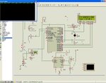
I have attached the code and the schematic of my project. The Proteus simulation works perfectly fine but the hardware isn't working at all. The LCD displays black boxes in the bottom row. Have checked the connections again and again but still no luck !!please help... schematic.jpg
 

Attachments

  • code.txt
    1.3 KB · Views: 72

What troubleshooting have you done, and have you isolated it to any particular area?
 

Hi,

If your lcd has a backlight on pins 15 / 16 you usually need a limiting resistor rather than 5v direct.
For now just disconnect the pin 15 in case the backlight is drawing too much current and affecting the pic.

Its hard to say what the problem is, the circuit diagram does not even have any component values.

Why not post your .dsn, and hex file so we can check it out properly
 
I have attached the DSN and hexfile. I tried removing the pin 15/16 . Still no luck!!It shows black boxes ..
 

Attachments

  • Project.rar
    23.1 KB · Views: 57

Sounds like you need to adjust the contrast.This is normally done by having a 10K pot wired between the supply with the wiper going to pin 3 on the display.
 

Hi,

Got your design to work in that the lcd does work, however there are other error messages relating to the rs232.

As you can see from the picture I have shown the 10k contrast pot, usually if you can see black blocks it means the lcd is working but the program code is not correct, though it could be the contrast is so strong you cannot see the text.

Have also amended a few other things, notice the +5v input, no need for batteries.

The single led had 10k , far too big, 330r only.

You can use hyperterminal to act as a pc for your comms.

Although pins 1,2 &3 of the lcd are connected to power and that 10k pot they are not needed in Isis simulations, the same applies to the crystal and 22pf caps.
Your set the frequency by right clicking the Pic and entering the value in the Edit box.

Not sure, but think the caps on max232 are not needed either.

Afraid I cannot help you on the source code, is it Basic ?
 

Attachments

  • ScreenShot002.jpg
    ScreenShot002.jpg
    142.2 KB · Views: 87
Hi,


D0 to D3 on the lcd are usually left open circuit, however, on some lcd you may need to pull them up to +5v with a single 10k resistor, also try pulling them all to ground by a 1k resistor.
 

I tried grounding D0 to D3 and also pulling them up to +5v. Still no luck!I also connected the 10k pot and tried to vary the pot but it shows black boxes or no boxes as i vary the pot . Yes the code is in basic.I changed the led resistor to 330. :) will figure out the rs232 errors but someone please help with the LCD.
 

Hi,

The only other thing to check is that pin5 of the lcd is connected to 0v, if it is not then the display will not work.

Is your crystal and caps connected close to the pic chip ? - are you using a breadboard ? the thin leads of those parts can loose the signal in the breadboard.
If so solder them onto a strip board and fit three thicker leads to connect to the breadboard.

Then do a simple flashing led to prove the pic and crystal work ok.

If the hardware seems fine , then suggests you try and find some simple lcd only code to test things on as your progeam code may be at fault.
As I said I do not know Basic , not sure if this code is compatible you complier.
https://melabs.com/samples/PBP-mixed/lcd.htm
 
Hi,

I have checked the connections. They are okay. I have created a layout for my circuit using eagle and tried it . Wasn't getting any result so tried it on bread board. The code simulation works perfectly fine in Proteus. Changed the crystal oscillator also. The suggested code is compatible, I have learned from this site only. Can't figure out the problem . :(

I guess I need to change the Microcontroller. Please point out if u find any other problem.

Thanks a lot for your help!:)
 

Have you confirmed the microcontroller portion is functioning? As wp100 mentioned?
"Then do a simple flashing led to prove the pic and crystal work ok."
Otherwise, on what basis do you guess that you need to change the microcontroller?

Or are you going to randomly replace components?!
 

I don't have a programmer at home. Need to use the one in college . I have my project submission next week so don't have much time. I don't have the privilege to program and test the microcontroller seperately . So will have to change the microcontroller . Have checked the LCD using Arduino and it works. So the only problem can be microcontroller i guess
 

I am compiling my code using Microstudio. After successful compilation the hex file is generated. I have a Unipro programmer. Can anyone help me with programming the microcontroller successfully !Thanks in advance !:)
 

problem solved!The LCD want getting initialized !sorted out!!:D
 

Status
Not open for further replies.

Similar threads

Part and Inventory Search

Welcome to EDABoard.com

Sponsor

Back
Top