Continue to Site

Welcome to EDAboard.com

Welcome to our site! EDAboard.com is an international Electronics Discussion Forum focused on EDA software, circuits, schematics, books, theory, papers, asic, pld, 8051, DSP, Network, RF, Analog Design, PCB, Service Manuals... and a whole lot more! To participate you need to register. Registration is free. Click here to register now.

Has anyone got a mechanical specification of N connector - probably a MIL standard?

Status
Not open for further replies.

DeboraHarry

Full Member level 5
Joined
Dec 3, 2011
Messages
274
Helped
48
Reputation
94
Reaction score
43
Trophy points
1,308
Location
UK
Activity points
3,905
I'm looking for sufficient information about the N connector such that I could model one in HFSS, or better still get someone to make one from a drawing, rather than copy one. In other words, I'm looking for a fully dimensioned drawing.

Can anyone help?
 

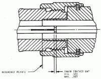
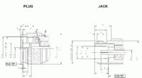
MIL-C-39012C (page 31) might help; it's available on the 'net.

Reputable connector manufacturers (Amphenol, H + S, Jyebao etc) have downloadable drawings showing dimensions of their products; these will show hole sizes etc.

These drawings plus the MIL-spec should provide enough information to draw/build your own.
 

MIL-C-39012C (page 31) might help; it's available on the 'net.
Thank you It only appears to have the female though.

Reputable connector manufacturers (Amphenol, H + S, Jyebao etc) have downloadable drawings showing dimensions of their products; these will show hole sizes etc.

These drawings plus the MIL-spec should provide enough information to draw/build your own.

I had tried a few manufacturers and could not find the detail I wanted. The MIL standard looks more like what I wanted, but it only seems to have the femals for all connector types - N, SMA. SC, C etc.

I don't actually want to build them - only simulate the electrical characteristics of them when left open.
 

Apologies; I should have directed your attention to pages 40 & 49.
 

The purpose of the MIL specifications is to define the connector interface exactly, the hidden internal details are up to the manufacturer. In so far, the MIL standard isn't a blue print to make a connector or "a fully dimensioned drawing".
 

I did say that manufacturers' " ... drawings plus the MIL-spec should provide enough information to draw/build your own".

For example, the Amphenol "Customer Drawings" shown here;

**broken link removed**

provide the "hidden ... details" (flange size/bolt circle pcd etc) for that maker's connectors.

Many dimensions such as bolt circles and fixing threads seem to have become de facto standards; I am not aware of any "real" standards for those kinds of dimensions.

I understand that the OP doesn't wish to actually build connectors; he simply requires dimensioning sufficient to allow them to be built, in other words, sufficient to allow them to be modelled.

I'm also a machinist in a modest way; I'm sure that I could make N(f & m) connectors from the MIL-spec and a manufacturer's drawing.

But I wouldn't like to; it would take days and a lot of money to make something that I can buy for a few dollars ! :)
 

provide the "hidden ... details" (flange size/bolt circle pcd etc) for that maker's connectors.
I've been talking about hidden internal details on purpose. The dimensions that are necessary to model the connector but are not specified in the MIL standard or manufacturer's drawings.

Saying these internal dimensions aren't given in the drawings doesn't mean they are hard determine. But it might be necessary to copy them.
 

I'm afraid that I don't understand what you mean by "hidden internal details"; can you elaborate please?
 

I can't believe that it's so hard to understand. See the said page 49 MIL STD drawing and a manufacturer's drawing. In a short, the MIL drawing doesn't show the internal design of a cable connector at all, it might be referring to an air dielectricum connector. The manufacturer's drawing does show the principle shape of the PTFE part holding the center pin, but not it's dimensions. That's the point.


P.S.: Strictly spoken, the MIL drawing is even misleading, because it suggests an isolator around the pin interface. As we know, it's just air. That's necessary to achieve 50 ohm impedance in this part of the connector.
 

The impedance of the N-connector is specified as 50 ohms in the MIL-standard; that directs the manufacturor to design the "hidden" parts accordingly.
 

The impedance of the N-connector is specified as 50 ohms in the MIL-standard; that directs the manufacturor to design the "hidden" parts accordingly.
I absolutely agree, that's what I meaned with my comment in post #5. Unfortunately DeboraHarry seems to be looking for exactly the part of information not contained in the standard.
 

Status
Not open for further replies.

Part and Inventory Search

Welcome to EDABoard.com

Sponsor

Back
Top