Continue to Site
Follow along with the video below to see how to install our site as a web app on your home screen.
Note: This feature may not be available in some browsers.
That is what bugs me a lot.Can you elaborate it more?but energy stored in the inductor delays the current peak, and the point where it finally droops.
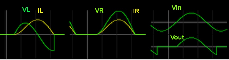
The applied voltage is well past its positive peak and is falling back towards zero.
The current starts to fall off too, but energy stored in the inductor delays the current peak, and the point where it finally droops.
It would drop at 180 degrees if there was no resistor, just a pure perfect inductor.
It would drop at 90 degrees (and follow the voltage) if there was just the resistor and no inductance.
With both, it drops somewhere between 90 and 180 degrees depending on how much R and how much L (in proportion).
When you apply a voltage across an inductor, the current ramps upward. The higher the voltage, the faster it ramps up.That is what bugs me a lot.Can you elaborate it more?
You are asking why isn't the slope VL at the input V zero crossing or Why isn't the "peak" shift" exactly 90 degrees between VS and VL on your top trace."why the current starts dropping at the circled point.Shouldn't it drop at 180 degree?"
