Continue to Site

Welcome to EDAboard.com

Welcome to our site! EDAboard.com is an international Electronics Discussion Forum focused on EDA software, circuits, schematics, books, theory, papers, asic, pld, 8051, DSP, Network, RF, Analog Design, PCB, Service Manuals... and a whole lot more! To participate you need to register. Registration is free. Click here to register now.

half wave rectification circuit with diode and load resistor

Status
Not open for further replies.

yellowmania

Junior Member level 1
Joined
Feb 2, 2012
Messages
16
Helped
0
Reputation
0
Reaction score
0
Trophy points
1,281
Activity points
1,407
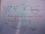
I have a circuit with a 12V AC supply adapter frequency of 50Hz, one diode and a 100K Load Resistor all in series. i have set the multimeter to DC like instructed and i have measured the voltage across the load resistor to be 5.8 Volts but i'm rusty on the theory as to why i have gained this value. As the supply is 12V and the wave is half rectified is it simply a case of half waveform half voltage? or is there more to it, Any Ideas would be helpful!
 

Have you any filter capacitor in your circuit.

If you connect capacitor 10µF...... parallel with load resistor 100kohm
you should get about 16Vdc reading in multimeter.
Remember to check polarity and voltage rating in electrolytic capacitor.
 
Last edited:
Hello yellowmania
I'm completely agree with kak111 .
and i think too , you should build them , in parallel with together.
Good luck
Goldsmith
 
2012-02-05 15.13.58.jpg

In this figure, i have shown why you get 5.6volts. As others suggested, you should use a parallel cap with your load.
 
yeah the next section of the experiment was to use a capacitor in parallel which ive completed. Thanks for all the help, i was completely lost before reading all the posts, it has really helped my understanding.
 

Status
Not open for further replies.

Similar threads

Part and Inventory Search

Welcome to EDABoard.com

Sponsor

Back
Top