Continue to Site

Welcome to EDAboard.com

Welcome to our site! EDAboard.com is an international Electronics Discussion Forum focused on EDA software, circuits, schematics, books, theory, papers, asic, pld, 8051, DSP, Network, RF, Analog Design, PCB, Service Manuals... and a whole lot more! To participate you need to register. Registration is free. Click here to register now.

Half-bridge SMPS without current sense transformer.

Status
Not open for further replies.

grizedale

Advanced Member level 3
Joined
Jun 13, 2011
Messages
838
Helped
17
Reputation
34
Reaction score
17
Trophy points
1,298
Activity points
8,804
Hello

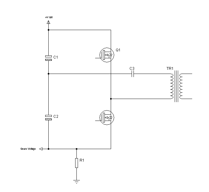
I must do half-bridge SMPS with vin = 390V and power = 200W

It must be very cheap so i dont want to have a current sense transformer as its expensive.


Instead i widh to have a current sense resistor, connected from the half bridge ground, back to the ground of the PFC
stage........i.e. the current sense resistor voltage goes below the ground of the half-bridge controller.
-howver, i cannot find a controller like this for half-bridge.

do you know why they don't exist.

This type of current sensing exists for LLC resonant controllers as in FAN7621.
 

with a half bridge you will onlysee current in a series gnd resistor when the bottom fet is conducting (if you put it in the right place) you won't see much when the high side fet is on - also you can't use current mode with a half bridge as the voltage on the rail dividing caps will quickly go to pos or neg under current mode control - you could try a 200W flyback, or a push pull with 800V fets if you want to use current mode,

Finally you can use average current mode control by looking at your o/p current on the sec side and using this inside a volt control loop to control the primary PWM (via an opto) - this gives very good results - there are some good app notes and papers on ave current mode control on the TI website (or just google it)
Regards, Orson Cart.
 
Last edited:
Hi Orson,

I think you are talking about a sense resistor in the source of the bottom fet of the half-bridge.

-this is accepted, though is not what i am referring to.

I am talking about a resistor actually in the ground retrun of the whole half-bridge controller........in this position this sense resistor will indeed see the current whether it went through the top fet or the bottom fet.

...most CCM PFC chips use this kind of current sensing, but i cannot find a half-bridge chip with this set-up
 

Yes a resistor in the ground path is common for low power PFC control, but I'm not sure about half bridge. In half bridge, the high frequency switch currents can flow through the input capacitor bank easily (there's no large input capacitor bank in a PFC), though the low frequency portion of the currents would flow through the ground return. So I don't think such a current sense would work for current mode control (in which you need to see the inductor current), but it might be effective for average current control, or for just average input current limiting.
 
mtweig is correct, for cycle by cycle peak current mode control (one of the safest control forms) only a current sense that sees the fast currents in the fets will work - as prev stated peak current mode cannot be applied to a half bridge without other means for correcting the voltages on the rail splitting caps - Regards, Orson Cart.
 
Hello,

I appreciate your comments, though i am not interested in current-mode control.

I am just interested in having a voltage mode half-bridge converter with primary-side current sensing, so that an overcurrent situation can be avoided.

-As you know, large load transients can result in overcurrents in the primary side of a half-bridge converter.
 

Hi,
Tie the negative end of the lower bulk capacitor and source of the low side MOSFET together. Connect a resistor between this point and the negative point obtained from the rectified mains. Use a 1k resistor, connecting one end to the joined point mentioned above and a 0.1uF and 10uF cap in parallel between the other end of the resistor and ground. Use an op-amp to amplify the voltage and use a comparator to compare the voltage across the resistor with a set voltage (that for the maximum load). When the voltage across the resistor is higher, the comparator can turn on an SCR that shuts down the controller (SG3525, TL494, etc). Since an SCR is used, you need to reset the power to turn the converter on again.

I haven't tried this, but I think this might work.

Hope this helps.
Tahmid.
 
Thankyou Tahmid,

-that sounds like an excellent idea.
i dont know why i havent thought of that.....its exactly the function i want.

i certainly see no reason why it shouldnt work.
 

while this might work for some types of overcurrent in the output, it will likely be too slow to protect against a short on the output - this is why CT's are so commonly used to measure current in a switching converter - so that over current protection can kick in within a few switching cycles to limit the o/p and protect the fets, Regards, Orson Cart.
 
Hi,
Tie the negative end of the lower bulk capacitor and source of the low side MOSFET together. Connect a resistor between this point and the negative point obtained from the rectified mains. Use a 1k resistor, connecting one end to the joined point mentioned above and a 0.1uF and 10uF cap in parallel between the other end of the resistor and ground. Use an op-amp to amplify the voltage and use a comparator to compare the voltage across the resistor with a set voltage (that for the maximum load). When the voltage across the resistor is higher, the comparator can turn on an SCR that shuts down the controller (SG3525, TL494, etc). Since an SCR is used, you need to reset the power to turn the converter on again.

I haven't tried this, but I think this might work.

Hope this helps.
Tahmid.
1K is pretty huge for a current sense resistor. Though the idea of bypassing with parallel capacitors might lower its loss a bit, it will still conduct all the DC.

Again grizedale, these methods aren't really suitable for fast overcurrent protection. Depending on the specifics of your system, it may not protect your transformer or switches from short circuits.
 
I didn't mean that the 1k should be the sense resistor. The sense resistor could be 1R, 0.1R or even 0.01R. 1k and capacitors are to filter spikes.

Hope this helps.
Tahmid.
 
A sense resistor placed in the way that Tahmid kindly described, would be the fastest, safest and best way of quickly detecting primary side overcurrents in the half bridge.

....that is obvious because it is right in the primary current flow.

...all it would need would be a pwm controller with current sense shut-off (i.e. FET off when overcurrent occurs as opposed to current mode control)
 

...all it would need would be a pwm controller with current sense shut-off (i.e. FET off when overcurrent occurs as opposed to current mode control)

Or you can use a comparator as stated above. And use this to shut down the PWM controller.

Hope this helps.
Tahmid.
 
because Tahmid's description puts the sense resistor between the neg point of the bridge rectifier and the bulk cap - it will not see the fast/large currents that appear immediately following a short circuit on the o/p (between the bulk cap's and the fets), from experience and observation I can say it will be too slow to protect the fets, if the sense R was between the bulk cap and the bottom mosfet source then it would see the true fet current for the low side fet only - but would not see the true high side fet current, and so would be half useful, regards, Orson Cart.
 
I didn't mean that the 1k should be the sense resistor. The sense resistor could be 1R, 0.1R or even 0.01R. 1k and capacitors are to filter spikes.

Hope this helps.
Tahmid.
Ah okay, the 1k is just for a low pass filter, I misunderstood.

A sense resistor placed in the way that Tahmid kindly described, would be the fastest, safest and best way of quickly detecting primary side overcurrents in the half bridge.

....that is obvious because it is right in the primary current flow.
No it's not in the primary current flow. And it's not as fast as being in line with one or both of the switches, or in series with the primary. I can guarantee that if you get a short on the output, the input will not react within on switching period. Or probably several, for that matter. Whether it acts before the supply destroys itself is unknown. Depends on the characteristics of the transformer, and the FETs. Anyways, you just need to determine what response speed you need. 100us, 1ms, 10ms... all are useful for some faults but not for all faults.
 
Last edited:
Hi

I have just sketched a half bridge and have confirmed to myself that a sense resistor, placed between the bulk input cap ground, and the ground at the bottom fet would catch all of the primary current, whether it flowed thru top or bottom fet.
...i thought and still think this was what Tahmid kindly said.....or as good as said.

Whichever the direction of current in the primary, the current is flowing in a loop from the primary bulk cap....so i cannot understand how Kirchoff's current law is being disobeyed here.(?)

i would reiterate that a current sense resistor at the primary side, placed in the right place, can do everything that a current sense transformer can do......so why , when the power is only 200W say, would you want the expense of a current sense transformer.?

...granted at very high powers you need a current sense transformer because a simple resistive-only current sense would consume too much power.
 

You can't measure the primary current with a sense resistor that is ground referenced, to be specific. To truly measure the primary current, the sense resistor has to be in series with the primary itself, and neither side is ground referenced at all times. If you don't mind having a good diff amp, then you don't need the sense resistor to be ground referenced. But often such a good diff amp (which needs very high CMRR at high frequencies) is very difficult to design or expensive to buy.
 
perhaps grizedale dosn't realise the bulk cap is split in two for a half bridge, and the top cap supplies all the fast/peak currents via the top mosfet to the transformer - it is only when the top cap recharges that you see current in a resistor which has one end connected to the neg o/p of the bridge rectifier. In a non pfc psu this could be 7mS later, Regards, Orson Cart.
 
Just to clarify, this is what I meant. I think all the current should pass through the sense resistor.


Hope this helps.
Tahmid.
 
Just to clarify, this is what I meant.
Yes, Orson has commented in post #14 about the disadvantages. Reviewing the original post, no clear purpose for the current measurement has been given yet. Without it, all assumptions about needing a fast measurement, preferably applied to both outputs transistors are void in part. I agree with Orson, that overcurrent or short circuit protection would require to measure the instantaneous output for both current pathes, and I would tend to assume it as a standard. Otherwise, we can ask why current is measured at all.

The suggested "half-useful" solution would place the sense resistor in the low-side transistor source connection. But of course, measuring the average output current as suggested by Tahmid can be reasonable, too. It gives access to the real input power of the inverter, which will be almost identical to the output power. If the instantaneous output current shall be measured, one would possibly think about a floating measurement at the bus capacitor tap to avoid two sense resistors.

P.S.: A simple Talema current transformer is around $1 and should be considered as well. You can also implement a Rogowski coil in your PCB, but the electronic effort (sensitive integrator amplifier) is somewhat higher.
 
Last edited:
Status
Not open for further replies.

Part and Inventory Search

Welcome to EDABoard.com

Sponsor

Back
Top