Continue to Site

Welcome to EDAboard.com

Welcome to our site! EDAboard.com is an international Electronics Discussion Forum focused on EDA software, circuits, schematics, books, theory, papers, asic, pld, 8051, DSP, Network, RF, Analog Design, PCB, Service Manuals... and a whole lot more! To participate you need to register. Registration is free. Click here to register now.

H-bridge IGBT inverter problem on motor

Status
Not open for further replies.

nadre25

Member level 3
Joined
May 15, 2009
Messages
56
Helped
0
Reputation
0
Reaction score
0
Trophy points
1,286
Activity points
1,780
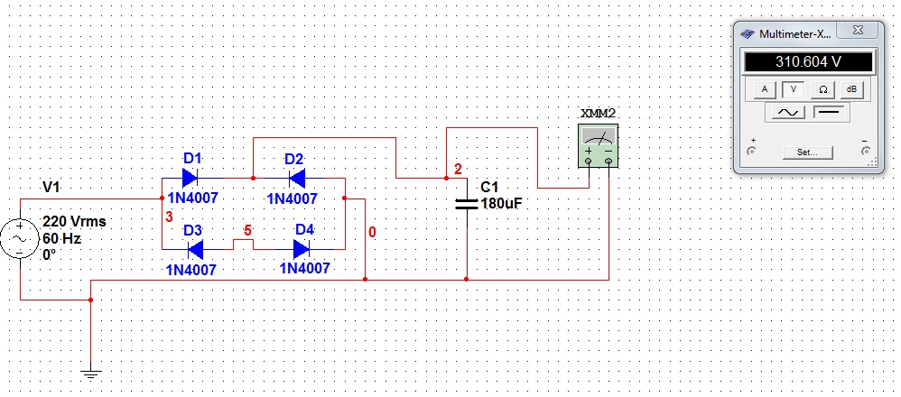
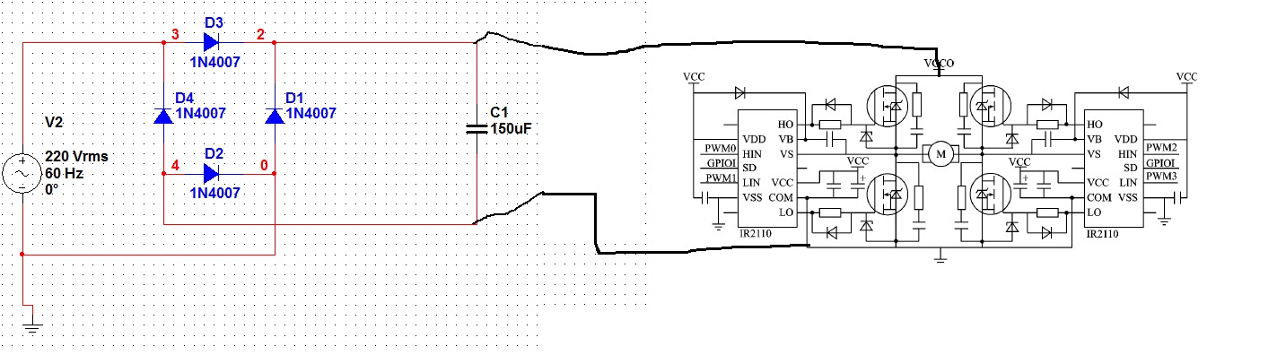
Our H-bridge IGBT inverter with DC rail of 315V is working on an industrial fan with voltage of 230VAC across it.

now when we used the same circuit in running our refrigerator, given that the voltage across out inverter is 230VAC, the refrigerator wont start and started clicking. we think its the "relay"

When we measured the voltage across out inverter, it read around 30-40VAC only, can anyone tell us where the 200V went? thanks.
 

The load inside the refrigerator is a motor attached to a compressor. That means you'll need a large start-up current to get the motor turning, and your inverter may not have the energy capacity to supply that peak current before the voltage output sags. Wire up a current shunt in series with the fridge (connected to the house 220V), and monitor the start-up current with an oscilloscope. See how much peak current you need to supply, and for how long... then beef up your inverter.
 

I think your circuit "sees" a large load presented by the motor, which requires a larger torque than you think. Then you will need to drive a larger current to start the fan.

One thing you need to take note. Dealing with such load, you will need to provide sufficient OFF time of any current path driven by a diagonal pair of IGBT to let the motor to lose retention, before you switch ON the current path for alternate pair of IGBT. Otherwise, you will have a very hot motor and you will hear scary noises, or worse your IGBT may blow.
 

Ok, how would we increase our supply? Do you have any suggestion for a High Voltage supply circuit?

This is our current schematic.... we used this since it has no transformer


we saw something about "Voltage Doubler" Circuit. Is this circuit good enough?
 

this is simple bridge rectifier ciircute for converting AC-DC,what you need is H-bridge driver.
 

what do you mean H-bridge driver?
 

since you are having your 315v dc rail voltage,i dont think your problem is from the supply,i could be from your driver or you did'nt connect the feedback loop from the final output to your oscilator.
 

Hi kabiru. what do you mean by we didnt connect the feedback loop?
 

yes,for your inveter to work properly you need to connect the feed back loop for voltage stability.
 

Two comments.

- the DC bus isn't a supplied by a full wave rectifier, as the circuit in post #4 seems to indicate at first sight. It's just a half-wave rectifier, three of four diodes are useless. So the supply voltage will considerably drop under load. Or the schematic is not representing the real circuit.

- apparently, the inverter is operated with a fixed sine pwm or square wave. Otherwise nadre25 would know, what's meant with feedback loop. You should clarify the actual H-bridge control waveform, however.
 

Hi FvM, sorry for the confusion.
here is post #4 and #10 we combined it actually.

The transistor inputs are SQUARE WAVES. The H-bridge creates an AC voltage due to alternate switching of the transistors as we have programmed.

since u mentioned that there was something wrong w/ the circuit on post #10 this is how we actually made it.

- The VCC of the H-bridge circuit is different from the VCC of the IR2110 drivers. VCC on the drain of the IGBTS is our rail voltage, approx 315-310V DC.


we have a question about the grounding of this supply and the H-bridge circuit.

1. Should the connection between D4 and D2 be grounded as well? ( or is there something wrong w/ our voltage supply)

2. If it is, should the ground be the same as the ground of the H-Bridge Circuit???

3. Again, what do you mean by "feedback loop?" are we suppose to connect something to something?

Thanks a lot!
 

1. Should the connection between D4 and D2 be grounded as well? ( or is there something wrong w/ our voltage supply)

2. If it is, should the ground be the same as the ground of the H-Bridge Circuit???
The new circuit from post #12 is a correct full wave rectifier, in contrast to post #4 and a similar circuit from a previous thread. "Grounding" to which ground? If the input voltage is from your regular grid (e.g. a wall outlet), it already has a grounded N terminal. Grounding the DC side would cause a short in this case. Unfortunately, this means, that the DC bus has a superimposed AC voltage and measurements are difficult. Or do you use an isolation transformer in front of the rectifier?

3. Again, what do you mean by "feedback loop?" are we suppose to connect something to something?
The feedback loop thing refers to a means to adjust the inverter output voltage, e.g. by modifying the PWM duty cycle respectively the sine modulation. I don't think, that it's available in your design.

The problem you reported won't be solved by a feeback loop, however. It's about the ouput voltage dropping down to a fraction. Did you measure the bus voltage in this situations? If it's still at 250 to 310 V, there must be a serious problem with the H-bridge.
 

- Yes our input voltage come from the outlet.

- we didn't use an isolation transformer before the rectifier. what you see in our schematic is our actual circuit.

- We can still adjust the PWM duty cycle through programming, just an info... we used 5kHz switching speed

- We measure the Bus voltage when the load is the electric fan. the reading of the bus from 315VDC went down to about 310-308VDC ( depending on the duty cycle that we use, we are able to increase and decrease the AC voltage entering the FAN the range is about 110-230VAC

note: we are able to change the duty cycle through a supply input in our PIC microcontroller.

- We also measured the Bus voltage when its the refrigerator. The reading of the bus is almost the same 310-260 (for some reason, if the refrigerator is the load, the BUS fluctuates a lot, compared to the electric fan) voltage entering the compressor is about 30-50VAC fluctuating
 
Last edited:

Assuming, that you still aplly correct gate drive waveforms in the refrigerator test, the most likely explanation is, that the bootstrap supply is dropping somehow, falling below the LVLO treshold of the gate drivers. But to effectively narrow down the problem, you would need to measure the respective signals with a differential oscilloscope probe. It's difficult to do a remote diagnosis.
 

So your saying i should check the HO and LO pins of my driver when the load is the refrigerator?

we are hearing a ticking noise, so be believe we must be inputting something in the refrigerator.

we just have a theory that our voltage rail might lack the current needed to run the compressor in the ref. would you have a suggestion as to how to increase the current of our rail? given our schematic.

Tnx!
 

315V DC power supply current problem.

Hi this is our H-Bridge Circuit and our Voltage rail. The full bridge rectifier is our supply voltage which outputs 315V DC

Our load was an electric fan and the fan ran well with 230VAC output.

However when we tried this on a compressor of a refrigerator, the refrigerator did not start. We only hear a ticking sound... we think its the relay.

The output voltage was only 30-50VAC and it was fluctuating. The inputs of the transistors are squarewave.

We think its because there is not enough current from our full bridge supply that is why the ref is not working, is there a way to increase the current of our supply?

Any possible solutions to the problem?

Thanks!

"315V DC power supply current problem" thread merged in this thread, you are having the same problem [alexan_e]
 

Yes, you should check the gata signals, provided you have suitable measurement tools.

I see, that the "cut-in" current of usual compressors is specified around 6 or 7 A, and rated current in a 1.5 to 2.5 A range. So the 1N400x input rectifier may be overloaded, don't know how about the H-bridge transistors? There's a ceratin risk, that after you manage to operate the inverter, the rectifier or H-bridge will be seriously damaged by overload.

P.S.: To refer to the problem of insufficient bus supply explicitely. Besides possible overload of the input rectifier, the rather small capacitor will make the bus voltage drop to almost a fullwave rectified sine. Although most likely unwanted, it won't cause the H-brife to fail. Or have you implemented a voltage supervision, that shuts down the inverter in thsi case?

For a reasonable operation with higher load, you would want to increase the rectifier rating to e.g. 6 A and increase the bus capacitor.
 
Last edited:

We used a bridge rectifier which is 35A, 600V. We just used the 1n400X for multisim to see our schematic.

a side question. If there is a rating in the data sheet of the rectifier that says "35A,600V" does that mean that is its maximum limit when it comes to its input?

Are you saying the value of the capacitor we used is wrong/insufficient? what value do you suggest? (the rating of our capacitor is 450V)

Thanks!
 

Rated current of a rectifier is mainly matters for junction temperature in continuous operation. The device will be able to handle huge inrush currents (up to kA) and also short overload condidtions. A 35A rectifier will be surely sufficient for your design.

I thought it would be obvious, that my comment referred to the capacitance value of the bus capacitor. For a 500 W inverter, I would expect e.g. 1000 uF. But it depends on your specification for the acceptable 100 Hz ripple of the bus voltage.
 

Status
Not open for further replies.

Similar threads

Part and Inventory Search

Welcome to EDABoard.com

Sponsor

Back
Top