tsibos22
Newbie level 5
h-bridge for steper motor[SOLVED]
Dear freaks,
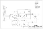
I found this schematic from the internet (https://sv1hag.blogspot.gr/2012/05/stepper-motor.html)
and i want to drive a stepper motor with an avr. The circuit works maximum at 24 volt but i want to drive my stepper at 34-36 volt(at 24 volts the stepper needs 0.7 Amperes). I read the datasheets and the transistors can works at 40 volts can i drive the stepper at 34-36 volts? I think that i need to change r5,r6,r7,r8 resistors. If i use 1.5K resistors will be ok? I use lm7805 to drop down the voltage 24->5 volts for the avr.
Best regards,
Tsibos

link image replaced with attached image of better resolution.
Avoid using images from external servers, attach them here.
alexan_e
Last edited by a moderator: