Continue to Site

Welcome to EDAboard.com

Welcome to our site! EDAboard.com is an international Electronics Discussion Forum focused on EDA software, circuits, schematics, books, theory, papers, asic, pld, 8051, DSP, Network, RF, Analog Design, PCB, Service Manuals... and a whole lot more! To participate you need to register. Registration is free. Click here to register now.

Gunn transceiver sensor

Status
Not open for further replies.

cyanpraveen

Junior Member level 3
Joined
Mar 31, 2011
Messages
27
Helped
0
Reputation
0
Reaction score
0
Trophy points
1,281
Activity points
1,527
hello guys,

Is anyone used Gunn transceiver sensor developed by microsemi.
I am using MO9081 gunn transceiver. i would like to know how to test the gunn transceiver

and how to check the speed variation through that sensor.
i also need to know the connection setting for that transceiver

check the datasheet for the mentioned component here

MO9081 | Microsemi

thanks for the reply...
 

I use a similar device.

To test it, connect a microameter to the detector output and feed the required voltage to the Gunn device. DO NOT USE A LOWER VOLTAGE THAN SPECIFIED - believe it or not Gunn diodes burn out if the voltage across them is too low.

You should see a small current flowing if the oscillator is ruinning. If you move a reflective object toward or away from the waveguide you should see a change in detector current.

Brian.
 
  • Like
Reactions: 9a3daa

    9a3daa

    Points: 2
    Helpful Answer Positive Rating
thanks brian. but the data sheet says i have to give pulsed DC input. how to give it. is it i have to connect any other component with the sensor to check it??
 

Check first with Microsemi but I would guess the 'pulsed DC' is just something it is optimized for. Given a steady voltage it would probably work equally well. Sadly they don't release V/I graphs or V/W graphs to check what would really happen.

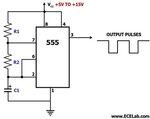
If you do want to pulse it, a simple NE555 timer can deliver enough current although it would be advisable to add a power driver stage after it to assist with the 100mA current the Gunn needs. The important thing to watch is the rise and fall time of the pulse. Gunn effect devices have a negative resistance property. Within a range of voltages, the current decreases as the voltage increases, this is contrary to Ohms law. If the voltage is lower than the recommended limits, the current could be significantly higher than normal and the diode could burn out. As long as the pulse goes from zero to full voltage quickly, the high current period will be short and quite safe.

Brian.
 

As u told i had tried giving pulse using 555 timer using this circuit circuit-astable-555.jpg
Input voltage: 7.5V (measured in multimeter or VOH meter)
Output at CRO : 7V (while measuring in multimeter or VOH meter it shows 4.8V).
But i cant able to see any current variation in micro ammeter when connected to o/p pin, more over i am getting 0 volt at output/mixer pin in the sensor.
kindly help pls
 

A normal meter will measure the average voltage at the 555 output, it's the peak that is important. Because some of the time the voltage is zero, the average will always be below peak. To measure the voltage, use a CRO connected across the Gunn diode bias with the circuit under load, in othe words, check the 555 is able to deliver the Gunn current, you should get a waveform with fast rising and falling edges and a peak of about 7V. If the voltage is lower than that, switch off, it means you need more current capability than the 555 alone can provide.

The voltage at the mixer will be very small, only a few mV, it is better to measure the current by connecting your meter between the detector output and ground and using a uA range.

It is important to understand how these devices work: The Gunn diode and the cavity it sits in make an oscillator circuit, the cavity has a small hole in it which couples some of the signal into a waveguide (the rectangular tube and flange). Sitting inside the waveguide and offset to one side is the mixer diode. The diode sees two signals, one is directly from the Gunn cavity and the other is coupled thrugh the waveguide from outside. Being a mixer, it produces an output signal which is proportional to the difference between these signals. So under static conditions, the output will be very tiny, what makes the signal bigger is a difference between the signals. Now consider normal operation, the module has a small antenna attached to it so it's beam width and gain can be set, the Gunn signal is directed out of the antenna into the area in front of it and some of the signal will reflect back into the antenna again. The mixer therefore sees two signals, one is direct frm the oscillator, the other is reflected from objects ahaead of the antenna but they are both at the same frequency so mixing them produces little or no variation in output current. Now, if anything moves in front of the antenna the reflected signal will travel over a shorter or longer path and Doppler shift will occur, this shift the frequency of the reflected signal and it no longer exactly matches the original Gunn frequency. The difference in frequency causes a signal at the mixer output, in fact it will be a frequency proportional to the rate at which the object moves, hence their use in radar and speed traps.

A simple test will prove this. Connect the module as I described and monitor the mixer current, an analog meter is best for this. Place the module on a table with the waveguide running parralel to the top so the signal is aiming level over the tables surface. Now place an object with an upright edge in front of the flange, something dense works best. Note the mixer current, now slowly move the object away from the flange, keeping it in line with the waveguide, you should see the mixer current rise and fall as the distance changes. This is because the reflected wave will add or subtract from the direct Gunn signal depending on the distance and therefore phase it reaches the mixer. There is a neat trick you can try: place a sheet of paper on the table and repeat the test, at each peak of mixer current, mark the position of the object on the paper. Afterwards, measure the distance between the marks you made, they should be exactly one half wavelength apart (remember the signal had to travel there and back so it passed twice the distance of your marks) from this you can calculate the microwave frequency of the oscillator.

Brian.
 

That really great explanation. thanks
But the problem is i am not getting any deflection in ammeter or oscillator.
as a result i got
Input voltage : 9.5V
555 Output : 9.0V
sensor input : 7.5V (I don't know why its coming like this?? because without connecting sensor i measured 555 output in CRO is 9V after connecting sensor i got only 7.5V)
Mixer output : -0.5V(square wave)
ON time : 1.4 ms
OFF time : 2.6 ms
as i mentioned earlier no deflection while i move the object in front of the waveguide.
 

The drop in output of the 555 from 9V to 7.5V is simply because the 555 is struggling to maintain full output while current is being drawn from it. The effect is normal although it suggests a current boosting stage after the 555 may be beneficial, however, this is not causing you to see no output.

The -0.5V you are measuring at the mixer proves the oscillator is running, there is no internal electrical path to conduct the Gunn diode supply to the mixer output so it must be the microwave signal causing the voltage. The reversed polarity also confirms this.

Do not measure the voltage at the mixer output, it's quite likely you have hit the voltage where the diode Vf is clamping the output so it can't change. Instead, measure the current flowing from the mixer pin to ground, it may only be a few uA so don't expect anything much higher. In normal operation there should be a resistor of between 1K and 10K across the output to make sure eough current flows that the voltage is kept low.

When used as a motion sensor, the mixer output is usually coupled through a capacitor to remove any residual DC then through a high gain amplifier (> x100) to turn the tiny variation in output to a more useable voltage. You should still be able to see some variation in the mixer current using just a meter though. Bear in mind that to see peaks and dips in the reflected signal on a meter you need to move very slowly, that why I suggested the paper and marker trick.

Brian.
 

    V

    Points: 2
    Helpful Answer Positive Rating
Thanks for conforming that my transceiver is working. But it seems still my problem persists. I am not even getting any deflection in µ ammeter. I had checked the ammeter and it is working properly.

I had borrowed another type of transceiver model no MO86735 (which has connected with 1k resister at output and 50 µF at input by default). when i give the input voltage it works perfectly and I can able to notice deflection in the form of sine wave at CRO itself when i move the object in-front of the wave guide. it looks like very simple in that model, but i don't know why i am struggling get like that in my Transceiver MO9081/MO9082.

Is that i need to connect any component with the transceiver like resister or capacitor to detect the motion sensing. If means can u say between which pins i need to connect these components
 

The 50uF across the Gunn supply suggests that module is DC driven rather than pulsed. I would be inclined to connect 7V DC across yours and see what happens, it should draw something in the region of 75mA and give a constant carrier out. Whatever you do, NEVER use a variable supply and wind the voltage up, it must be stable at 7V before you connect the Gunn bias or it will destroy the device. Strange though it sounds, Gunn diodes are negative resitance devices, over part of their voltage range the current they pass will decrease as the voltage is increased, if the voltage is too low the current can increase to a dangerous level and destroy it.

Something in what yu are saying doesn't seem right, you have -0.5V at the mixer output but no current is flowing? If you have a load resistor across the mixer output, and you should, and there is a voltage across it, there must be current flowing. Plain old Ohms Law tells us that.

The normal connections are:
The casting is always ground or 0V, this is the negative side of the supply.
Positive 7V, constant or pulsing is fed to the Gunn bias pin. Always connect a capacitor of say 1nF to ground close to the bias pin, add 10uF in parallel if you are using constant DC.
There should be a resistor of say 1K to 10K from the mixer output to ground, this may have a capacitor of say 1nF across it.
For motion detecting the signal is taken from the mixer output via a capacitor of about 100nF to a high gain amplifier.

Is this how you have it connected?

Brian.
 

I had just connected 3.3K load resister across the mixer output and ground. i didnt connect any capacitor.
i had measured input current is around 300mA. is this one can cause trouble in sensing motion??
 

300mA is probably far too much, normally it should be in the region of 75 - 100mA for a low power module like that. Please confirm this with the manufacturer as there are some Gunn devices that work at higher currents.

To recap:

You measure +7V with respect to ground at the Gunn bias pin and 300mA is being drawn.
You have a 3.3K resistor connected between the mixer outut and ground and you can measure -0.5V across it.

Is this how you see it?

Brian.
 

Yeah in that way only i had measured it.
The reason why i asked about the current rating is, as i mentioned previously the Gunn model MO86735 (sensor which detect motion sensing) data sheet also mentioned the max current range is 200mA but it worked with 300 to 400 mA.
So if the above mentioned sensor works with this current range means, obviously my sensor also need to work right.
If i am pretending wrong means, forgive me.
 
Last edited:

What is important is to understand how Gunn Effect Diodes work. A normal diode has a V/I curve which is offset from zero by a few tens of mV then rises exponentially. A Gunn diode has a different curve, as V increases so does I but then at a certain point the reverse happens. As V increases, I decreases, hence the name 'negative resistance', beyond a certain voltage the current starts to climb again. So instead of a V/I curve that just rises, a Gunn curve rises, dips then rises again. In order to oscillate the voltage has to be set so the working point is on the downward part of the dip, it looks from your measurments like you are operating beyond the dip on the second uphill part. If I'm right, the oscillator can not function, it will just sit there warming up and no signal will be produced.

Unfortunately low power microwave signals are difficult to observe. If you have a second module, you can try using it as a simple receiver. Do not power the Gunn diode at all, just connect a uA meter across the mixer output pin and the body of the module. If you point the waveguide flange toward the first module and about 20cm away you should see a current flowing. Placing your hand between them should make the current drop to zero because the signal wil be absorbed into you.

Brian.
 

To limit the input current from 400mA to 100mA, I have connected 100 ohm resister in series with the input voltage(7.5V). before connecting the resistor to the sensor I measure the current and voltage,
V= 7.5
I = 40mA.
But after connecting the resistor to input pin and i measure the voltage drops almost to zero.
Is this by any mean related to my sensor for not working properly???
 

Well, there are only two components in the module, one is the Gunn Effect diode and the other is the mixer diode. The mixer is a normal diode, you can check it with a diode test range on a multimeter. It looks like you might have fried the Gunn diode. Note my previous statements though, if you drop the Gunn bias voltage, it's current will increase and it could burn out. Although your 100 Ohm resistor theoretically limits the current to 75mA, you are measuring 'almost zero' across the Gunn device which means one of two things, either it is running in a high current mode and is vulnerable to damage, or, it is already damaged.

Brian.
 

Status
Not open for further replies.

Part and Inventory Search

Welcome to EDABoard.com

Sponsor

Back
Top