Continue to Site

Welcome to EDAboard.com

Welcome to our site! EDAboard.com is an international Electronics Discussion Forum focused on EDA software, circuits, schematics, books, theory, papers, asic, pld, 8051, DSP, Network, RF, Analog Design, PCB, Service Manuals... and a whole lot more! To participate you need to register. Registration is free. Click here to register now.

Gsm based home security system

Status
Not open for further replies.

prakash_kadri

Member level 2
Joined
Apr 11, 2013
Messages
42
Helped
0
Reputation
0
Reaction score
0
Trophy points
1,286
Location
Bangalore
Activity points
1,721
Hi Friends,

I am very much interested in doing project with Microcontroller(AVR-ATMEGA 16). However i am new to this field.So i dont know very much in detail about programming part.However with the help of google i purchased AVR programmer and SIM 300 GSM module.

I want to do GSM BASED HOME SECURITY SYSTEM.It should have the following option.

1)The system should be made of Atmega Micro controller-ATMEGA 16(As i heard it is more simple to program compared to other and also cheap)
2)The micronctroller should be linked to GSM
3)There should be LCD DISPLAY .
4) I should be able to store min 10 mobile numbers
5)The mobile number i should be able to enter/change using press
buttons.To change mobile number the system should be secured by
password.
6)It is enough if i have one NC or NO contact where i can connect my
triggering magnetic door switch.

When the door switch is triggered the system should dial 10 numbers
one by one with a gap of approx 1mint. The dialing should stop if any
one mobile number accepts the call.

I tried lot in google to find the C code but couldnot get.Can anyone please proved me the C code for the above Or similar project.

Thank you
 

You project is very simple but I have to know how you connect SIM300 board to MCU board? Through TTL pins or RS232 connector. Can you post a link for your SIM300 board? What is your MCU Clock?
 
I purchased SIM 300 Modem with RS 232, the details in the link; **broken link removed**
Also i purchased one development board for ATMEGA16, the MCU clock what you are referring is the spec of qtz crystal mounted near the MC?
 

I checked the development board which i have, it is written as KDS4.000 on the crystal Link :https://oricop.en.alibaba.com/product/517720534-213128059/KDS4_00MHZ_Crystal.html
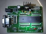
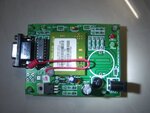
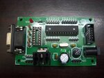
I have not connected any LCD, keypad or Relay etc...the development board has connector as Port A,B,C, and D. I have attached in this mail,the photo of development board and SIM 300 GSM.

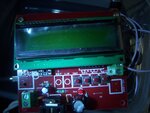
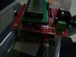
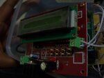
I also attached the pictures(3 pics) of the finished project which i purchased readymade from Bangalore.Keeping this as reference i want to build my own project.However i use AVR Studio 4, i burnt some simple programs like LED blinking , which worked fine.
100_4475.JPGSample 1.JPGSample 2.JPGSample 3.JPG100_4476.JPG
 

Your Crystal is 4 MHz. So, you want to use AVR microcontroller. You images are not helpful. Build your circuit first ie., connect LCD, Keypad, etc... to the required PORT(s) and post the circuit diagram. Then only Code can be written. Use Proteus from labcenter.co.uk to draw the Schematic. In trial version you cannot save the file but you can take the screenshot of the circuit.

If your PC has serial port (RS232) then connect your SIM300 board to it and issue GSM Commands and check if is working. Try to send SMS. If your PC doesn't have RS232 then use Serial to USB Converter and connect your SIM300 board to USB port of PC and test it.

What AVR you want to use?
 

Since my Atmega development board and SIM 300 GSM module has RS 232 connection(Picture in my previous msgs) i should use RS232 connection right?..Correct me if i am wrong.
 

hi..

I have been trying to check the SIM300 board with AT commands.I checked the SIM300 board by taking it to the supplier, it is working fine there.They told me to use TERMINAL software.but i coudnot connect with the SIM 300 board.As you suggested i purchased serial to USB converter.It is connected to COM3 in my system. But i couldmot get/Type COM 3 in TERMINAL software window .I also tried PUTTY and Hyper terminal.All has problem with Port connection.

Can you help me on this.
 

Use RealTerm. Mention how you have connected the two boards. Explain connection. You have to install drivers for USB to RS232 converter and then it will be listed in Device Manager. Right click it and choose properties. In one of the tabs PORT used will be shown. Use it in RealTerm.


Edit: See both ATMEGA dev board and SIM300 board. In SIM300 board I can see MAX232 chip next to DB9 connector but in ATMEGA dev board there is no chip in MAX 232 socket next to DB9 connector. You have to put a MAX232 chip into the IC socket.
 
Last edited:

ok..

1) Since the finished project(The photo attached in previous reply) was built using ATMEGA 8, this project also i want to build in ATMEGA8 ( Not Atmega 16) and also ATMEGA8 board is smaller.

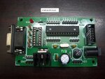
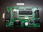
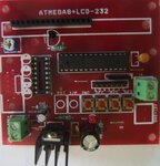
Today i purchased ATMEGA8 Dev board photo attached.The crystal used in 16MHz.

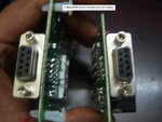
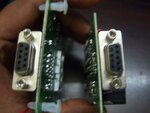
I will insert MAX 232 IC in the ATMEGA8 dev board.Also both the RS232 connection in the ATMEGA8 Dev board and GSM 300 in Female , how we connect this two(Photo attached) ?

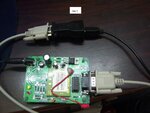
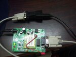
2) Regarding GSM 300 connection to PC, i attached photo(Step1,2,3).Please have a look on it whether i am on the right direction?
ATMEGA8 dev Board.JPGSIM300 and ATMEGA8 CONNECTION.JPGstep1.JPGstep2.pngstep3.jpg
 

Attachments

  • ATMEGA8 dev Board.JPG
    ATMEGA8 dev Board.JPG
    184.8 KB · Views: 93
  • SIM300 and ATMEGA8 CONNECTION.JPG
    SIM300 and ATMEGA8 CONNECTION.JPG
    155.2 KB · Views: 86
  • step1.JPG
    step1.JPG
    186.5 KB · Views: 94
  • step2.png
    step2.png
    285.8 KB · Views: 93
  • step3.jpg
    step3.jpg
    76.3 KB · Views: 89

major problem of usb to serial converter is that they may be duplicate or low quality Chinese material. either they have faulty hardware or they have old revisions of interface ic..
also many of them do not support windows 7...
check this link from prolific...
**broken link removed**
 
Hi..

I reinstalled the software, it looks like the issue is with the Serial-USB converter only.When i read the manual in the internet it also say's that the "Yellow Mark Error Code 10 in Device Manager under WinXP, Vista, and 7" is the symptom of Fake cable. So i will purchase new one, this week of different make and let you know.Meanwhile i checked this GSM in the supplier place only and it is working fine, also i tried to dial the GSM, the LED is blinking in the GSM board.

As you suggested i tried to draw a sketch in Proteus, I was able to do half of the sketch, but it became more and more complicated when i tried to introduce all the components into the PCB.
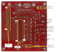
So i just scanned the board which gives the wiring diagram.I highlighted some important components in it.Let me know is this data enough to write the program?.

Also i have Atmega 8 Dev board, can we build the system using that?

ATMEGA8 dev Board.JPGPCB Top.JPGPCB-Bottom.png
 

Yes. You can use ATmega 8 dev board. Buy USB to Serial and TTL adapter from here **broken link removed**

It is a good one. I have it. Use the Green Atmega 8 dev board. Put a MAX232 in it and connect your GSM board to ATmega 8 board using DB9 connector. MAX232 will be connected to Rx and Tx pins of MCU on MCU side. So you can use it. Do you use Atmel Studio 6?
 

Status
Not open for further replies.

Similar threads

Part and Inventory Search

Welcome to EDABoard.com

Sponsor

Back
Top