Continue to Site

Welcome to EDAboard.com

Welcome to our site! EDAboard.com is an international Electronics Discussion Forum focused on EDA software, circuits, schematics, books, theory, papers, asic, pld, 8051, DSP, Network, RF, Analog Design, PCB, Service Manuals... and a whole lot more! To participate you need to register. Registration is free. Click here to register now.

Grounded CPW simulation using CST

Status
Not open for further replies.

Tan_Isn

Newbie level 3
Joined
May 13, 2011
Messages
4
Helped
0
Reputation
0
Reaction score
0
Trophy points
1,281
Location
Ukraine
Activity points
1,322
Dear all.
Although this topic has been discussed many times before, unfortunately, I have problems still.
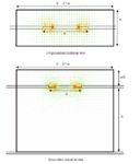
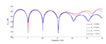
I have chosen different variants of port sizing(generally as in tutorial - see 1.png), different boundary conditions (the most appropraiate for this waveguide are as in 3.png ), but the desired result (see 2.png, taken from **broken link removed** ) is unreachable.

I would appreciate even small piece of advice, since I dont have any ideas what's wrong.
 

Attachments

  • 1.png
    1.png
    93.8 KB · Views: 144
  • CPW_14.03.rar
    23.7 KB · Views: 99
  • 2.png
    2.png
    50.5 KB · Views: 158
  • 3.png
    3.png
    40.7 KB · Views: 153

Can you maybe upload your design, because it's not so easy to answer this question from just some picture. E.g your result would also be interesting.

------------
Sorry, i see now your file! ;-)

- - - Updated - - -

Some hints: Be careful with symmetry planes, a CPW as more than 1 propagation mode. In your case there are 4 modes, 1 QTEM and 3 TE modes, with cutoff freq < 15GHz.

By the way, for which freq you want to use such long cpw with FR4 substrate?

If I have time later, i try to simulate your design.
 

Thank you for your valuable pieces of advice.
May I ask you some questions?
1) How do you know that there are "4 modes, 1 QTEM and 3 TE modes, with cutoff freq < 15GHz"? How is it possible to determine the magnitudes of these modes and their resonant frequencies?
For example in HFSS it is possible to build the dependence of gamma versus frequency.
2) What is the problem with magnetic symmetry plane?

The operation frequency is approximately 5.8 GHz.
The length of CPW makes up 6 wavelengths in order to prevent the interference between the waveguide ports.
Actually I would like to simulate BPF and the length of CPW would be much smaller. But firstly I should obtain CPW with appropriate characteristics.

Thank u)
 

When you place or ports, you can edit the properties of the ports. Under modes you can enter the number of max. Modes for simulation. After this, and if you are running a transient simulation, in port info windows you can see the propagation modes.

Depending on cpw structure you have also for e.g. Parallel plate modes. I don't know if they are correctly calculated with symmetry planes. Nevertheless, The symmetry plane is set correctly.

How you got this info about this 6 wavelength?
 

Actually my research adviser recommended according to the conventional soviet literature about microstrip lines placed in metal boxes.
If Russian is not a problem for you I can ask for more details. ;-)
Indeed when I simulate waveguides of different length the S-parameters become different.
However when I simulate the filter on CPW, increasing the length of it, the results are almost the same.
;-)
But the problem is in my CPW. I can't obtain the desired results. May be the problem is in high order modes?
 

I see you are from ukraine. We had some guys from ukraine at our chair. Nevertheless i can't understand ukraine or russian language.

The problem of cpws in literature is that there exist just a few really good books.

I can not before monday try to simulate your problem. But i think one big problem are the higher modes. You don't get some warnings?
 

Status
Not open for further replies.

Part and Inventory Search

Welcome to EDABoard.com

Sponsor

Back
Top