Continue to Site

Welcome to EDAboard.com

Welcome to our site! EDAboard.com is an international Electronics Discussion Forum focused on EDA software, circuits, schematics, books, theory, papers, asic, pld, 8051, DSP, Network, RF, Analog Design, PCB, Service Manuals... and a whole lot more! To participate you need to register. Registration is free. Click here to register now.

ground plane continuation between power components and low signal control

Status
Not open for further replies.

geoleomeo

Newbie level 6
Joined
May 11, 2011
Messages
11
Helped
0
Reputation
0
Reaction score
0
Trophy points
1,281
Activity points
1,360
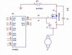
I am making a PCB for control of three 24 vols motors, 12 ampere each. I found in the original board that the designer separates the copper pour of the ground plane under the power components and the micro-controller components but they are still connected by a thin trace at some point while the designer could simply make it one plane. What is the value of this discontinuation while connection at one point??

Thank you
George
 

It sound like he is trying to control the high current paths to the motors, the ground have to be connected as it is the reference point for the design. On designs like this I like to have a good ground connection between the low level signals and the high power outputs. Design I have done in the past like this I have done either:
Two board designs, the power board with heavy copper (2oz plus, preferably 4oz) and a controller board with lighter wieght copper. This provides the best of both worlds, heavy copper to carry the current and a control board that can be galvonicly isolated. Also the smaller components in the control circuits cannot usualy be etched out of heavy copper.
Single board design with careful component placement, a full ground plane, but with slots to control the flow of the high output currents, this is harder to achieve but does create a simpler assembly. Care must be taken on component placement, connector positions, and adding slots must cater for signal integrity, EMC and the drive frequencies used and where the return current paths are going to flow.
 

...It sound like he is trying to control the high current paths to the motors...

That´s exacly the reason.
The most critical buses ( Analog / RF / Power / uC ) are generally geometrically separated to avoid induced currents.
However remains the need to keep them connected in order to don´t loss 0v (GND) reference.

Is common to use SMD 0R0 resistors, instead thin tracks.
When the noise amount becomes excessivelly dramatic, that resistor is defined with a non-zero empirical defined value.

+++
 
Thank you
I also found in the original circuit of the manufacturer an addition of small resistors and capacitors between the motor and the battery and the motor and the signal from HIP4082 as attached in the image.

What are the functions of these additions and what will happen if I design a circuit without them??

Is it important to put more small capacitors between the +bat and the ground even if I have 2 big 1200uF capacitors already?
 

Attachments

  • motor.JPG
    motor.JPG
    25.7 KB · Views: 114

The schematic snippet is rather incomplete and won't work without additional parts. Particularly, HIP4082 is a bootstrap driver, it only works with a modulated output, not 100% dutyl cycle and in combination with a low side switch. You should figure out the full circuit to analyze it. Or refer to the HIP4082 datasheet.
 

yes sure there is a complete circuit around it like the datasheet
I am just wondering why they put a capacitor and resistor between the source and drain unlike common circuits and also a capacitor between the drain and source

thank you
 

thank you that's very useful
But I think I can reduce that
 

Yes R2/C2 is a snubber network. It's not generally required in H-bridges, but may be useful, if circuit wiring inductances are high. C1 doesn't serve a resonable purpose in my opinion. You would rather increase the gate resistor, if you want to slow down the switching speed. It may be also a drawing error.

Low inductance bypassing of the DC bus voltage is essential, however.
 
thank you
Do you mean by low inductance bypassing a big capacitor between the battery
I have 2 capacitors 1200uF each near the FETs

---------- Post added at 20:30 ---------- Previous post was at 20:23 ----------

I also think there is something wrong in the datasheet of HIP4082
They show both AHI, BHI connected to 12 volt and at the same moment ALI, BLI are connected to the same PWM but inverted
Doesn't that cause the motor to turn left then right all the time !!
I thought that in case bothe AHI and BHI are connected to 12 volt, only one of the low inputs should be connected to pwm while the other to low and vice versa to control direction !!!
 

Do you mean by low inductance bypassing a big capacitor between the battery
I rather thought of smaller capacitors, e.g. 1 - 5uF foil or ceramic capacitor, in addition to a larger DC bus capacitor.
I also think there is something wrong in the datasheet of HIP4082
They show both AHI, BHI connected to 12 volt and at the same moment ALI, BLI are connected to the same PWM but inverted
Doesn't that cause the motor to turn left then right all the time !!
I thought that in case bothe AHI and BHI are connected to 12 volt, only one of the low inputs should be connected to pwm while the other to low and vice versa to control direction!
The datasheet schematic is implementing a commonly used bipolar PWM scheme. There are others as well, you're suggestion won't work however. The bootstrap circuit doesn't allow 100% duty cycle for an extended amount of time.
 

Thank you FvM

I meant that in the high part of the PWM, BL and AH are ON while BH and AL are OFF in which case the motor will move in one direction. In the low part of the PWM cycle the opposite will happen and consequently the motor will turn in the opposite direction and will not stop moving in the lower part of the PWM. Is that true?
And also in this case there is no way to invert the motor direction...
 

I found that the main reason they do that is that in case both high inputs are connected high, inverting the low inputs is the only way to avoid electronic brakes
 

Status
Not open for further replies.

Part and Inventory Search

Welcome to EDABoard.com

Sponsor

Back
Top