Ryner
Newbie level 3

- Joined
- Oct 7, 2013
- Messages
- 3
- Helped
- 0
- Reputation
- 0
- Reaction score
- 0
- Trophy points
- 1
- Location
- Singapore
- Activity points
- 25
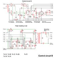
Hey guys, this is my first post here, and my professor has tasked me to do a Grid-Tie Inverter that involves these circuits:
1. IGBT Bridge
2. DC Link
3. Low Pass Filter
4. 200VA Transformer
· Driver circuit
· Sensing circuit
· Firing circuit
· PWM circuit
5. 200MHz carrier circuit
6. Reference circuit
· Synchronisation circuit
· Anti-islanding circuit
Currently, I have done some research as to how to connect these circuits, and I've managed to find a schematic that includes a large portion of the required circuits.

Could someone help me out with adding in the missing circuits? Your help will be much much appreciated! Thankyou!!
1. IGBT Bridge
2. DC Link
3. Low Pass Filter
4. 200VA Transformer
· Driver circuit
· Sensing circuit
· Firing circuit
· PWM circuit
5. 200MHz carrier circuit
6. Reference circuit
· Synchronisation circuit
· Anti-islanding circuit
Currently, I have done some research as to how to connect these circuits, and I've managed to find a schematic that includes a large portion of the required circuits.

Could someone help me out with adding in the missing circuits? Your help will be much much appreciated! Thankyou!!