Continue to Site

Welcome to EDAboard.com

Welcome to our site! EDAboard.com is an international Electronics Discussion Forum focused on EDA software, circuits, schematics, books, theory, papers, asic, pld, 8051, DSP, Network, RF, Analog Design, PCB, Service Manuals... and a whole lot more! To participate you need to register. Registration is free. Click here to register now.

Gray Square in my RF Module circuit in Proteus 8

Status
Not open for further replies.

easyglory

Newbie
Newbie level 1
Joined
Jan 22, 2021
Messages
1
Helped
0
Reputation
0
Reaction score
0
Trophy points
1
Activity points
9
1611297991574.png

How do I fix this circuit's gray dot (pin 17-yellow marked circle).The circuit I am trying to simulate is on the link I have mentioned ;
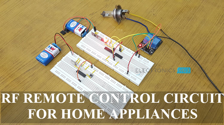
Please help. TIA
 

FvM

Super Moderator
Staff member
Advanced Member level 7
Joined
Jan 22, 2008
Messages
50,970
Helped
14,629
Reputation
29,534
Reaction score
13,733
Trophy points
1,393
Location
Bochum, Germany
Activity points
291,643
Don't know how the circuit behaves in Proteus, but you should at least copy it correctly. D5 flipped.
 

spudboy488

Full Member level 5
Full Member level 5
Joined
Oct 10, 2012
Messages
272
Helped
69
Reputation
140
Reaction score
76
Trophy points
1,308
Activity points
3,058
The gray square indicates the pin state is unknown (not high/not low). Fixing the LED (per FvM) may correct it or it might just be the way the part is simulated.
 

Status
Not open for further replies.

Part and Inventory Search

Welcome to EDABoard.com

Sponsor

Top