Welcome to our site! EDAboard.com is an international Electronics Discussion Forum focused on EDA software, circuits, schematics, books, theory, papers, asic, pld, 8051, DSP, Network, RF, Analog Design, PCB, Service Manuals... and a whole lot more! To participate you need to register. Registration is free. Click here to register now.
Strictly spoken, a waveform can't work as complete design spcification, because it tells only about specfic cases. In the present case, we can only guess, that the circuit performs a pulse extensions of 2 clock cycles under all condtions. There must be a describing text.
Secondly, the waveform must be unequivocal. The shown one is just the opposite, showing a timing that can't be implemented in a real circuit, because input edge, clock edge and output edge seem coincident. It seems to have been sketched carelessly, without considering real logic behaviour.
Thanks for reply. So , reverse engineering isn't possible here (need to have more details). We should have bit more information to extract circuit . I was asked this question in an interview (COSMIC CIRCUITS). But since i didn't knew answer , i asked for some hint. They told me that this circuit will have 2 flops. Secondly , they asked me to draw circuit which can stretch falling edge of input by 2 clock pulses ????
Saying the circuit has two flip-flops gives some details as well. The waveform needs to be sligtly corrected, then there can be an answer to the question.
Unlike real design problems, interview questions must not be unequivocal. They must only allow you to show your skills.
Strictly spoken, a waveform can't work as complete design spcification, because it tells only about specfic cases. In the present case, we can only guess, that the circuit performs a pulse extensions of 2 clock cycles under all condtions. There must be a describing text.
Secondly, the waveform must be unequivocal. The shown one is just the opposite, showing a timing that can't be implemented in a real circuit, because input edge, clock edge and output edge seem coincident. It seems to have been sketched carelessly, without considering real logic behaviour.
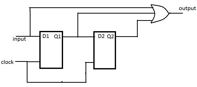
If you took the input and ORed it with output from a two-stage shift register, you would get the output shown here. But like everyone else has said, you need to be able to ask enough of the right questions to find out what the real design intent is.
My first answer is reflecting the general nature of the question "what should be approach for solving this kind of questions?".
A more reasonable question would be "what's the most simple circuit to implement the shown behaviour?". Apparently the actual interview question has been of this kind. If the interviewer is familiar with logic design, he'll also avoid timing violations brought up by the waveform.
Here is the solutions. this is very simple one. Hope this works.
Help me if its not correct. This was one of the question in an interview i have faced recently.
This site uses cookies to help personalise content, tailor your experience and to keep you logged in if you register.
By continuing to use this site, you are consenting to our use of cookies.
")