Continue to Site

Welcome to EDAboard.com

Welcome to our site! EDAboard.com is an international Electronics Discussion Forum focused on EDA software, circuits, schematics, books, theory, papers, asic, pld, 8051, DSP, Network, RF, Analog Design, PCB, Service Manuals... and a whole lot more! To participate you need to register. Registration is free. Click here to register now.

Get VSS from VDD. PLEASE HELP!

Status
Not open for further replies.

Combinu

Newbie level 6
Joined
Apr 19, 2011
Messages
14
Helped
0
Reputation
0
Reaction score
0
Trophy points
1,281
Activity points
1,388
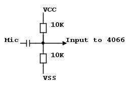
Hi, I am going to use the HCF4066BE IC.. This is a QUAD BILATERAL SWITCH FOR TRANSMISSION OR
MULTIPLEXING OF ANALOG OR DIGITAL SIGNALS.

The datasheet is over here: http://www.datasheetcatalog.org/datasheets/90/206772_DS.pdf

This type of IC does not work like a normal IC with pins 8, 16 connected to GND and VCC respectively, but it connects to VSS and VDD.

VDD is ok since it gets the normal +5V but VSS must have -5V so that the IC works. I tested and it does work only with these condition.

My problem is i am going to make a board and the only supply i have is +5V and GND (i am going to get them from the arduino). So is there any way that from this supply i get -5V too.

Its not a problem if i have to build another small circuit, but i don't need to introduce another outer supply. The only thing i need is a setup that from 5V i get -5V.
Please be basic in you explanation since i am a beginner.

Thanks and Regards
Combinu
 

You can still use the 4066 as a digital switch by connecting VSS to ground, its only for some analog signals it needs the negative supply. If you are using it for analog signals, it may still be possible to use a single supply if you offset the input voltage to 2.5V. The important factor is that the input voltage does not go below ground (negative with respect to gnd). The idea behind the + and - supplies is that an AC coupled signal or one ground referenced can pass through the switch and still have +/- excursions at its output pin.

There are good reasons for using both supplies if it is necessary, the switch's 'on' state resistance gets lower as VCC to VSS become greater and the linearity also improves. The current drawn from the negative supply is very small so you can easily generate it from the positive supply using an oscillator and rectifier or you can purchase ready made DC-DC inverter units.

Brian.

Thanks very much for you help it was very useful.
In fact i am going to use it as analogue and my voltages are going to be less then 0V with reference to the ground so i need to have the VSS less than 0V for sure.

I have two small questions... How should i connect the rectifier to invert the 5V of supply that i have?
Secondly do you know what is the product code of DC-DC inverters?

Thanks again
Combinu
 

Hi its again me... I have found the circuit attached below as an image.

It inverts the voltage as you can see also from the graph, but you can also see that the voltage is never stable i.e. reaching -3.3V

My qyestion is: Is this ok to get good analogue signals from the 4066 since the VSS reference is not stable or you get wrong results on the output of the 4066?

Secondly if it is not ok to have an unstable VSS for 4066 how can i modify the circuit so that i make is more stable?

Thanks & Regards
Combinu voltage-inv.JPG
 

... do you know what is the product code of DC-DC inverters?
I've successfully used the R05B05 from RECOM: datasheet download. It's small, already filtered, even 2 isolated ± voltages (what you wouldn't need). Got it for small money via eBay (search for DC-DC).
 

I was going to suggest a circuit just like that. It is producing almost -3V which is close enough but bear in mind that if you are running it off 5V, the output will also be about 5V. In theory, the voltage coming out is twice the voltage coming out of pin 3 minus the voltage drops of the diodes. Each diode drops about 0.65V so you lose about 1.3V in them but it is a constant. The output at pin 3 is proportional to the supply to the 555, if you increase the supply, the output becomes greater.

I think what you are seeing in your simulation is the 555 struggling to work on a 3.3V supply and then what it does manage to produce is dropped by 1.3V in the diodes, hence the lower than expected result. If you can run the circuit on 5V I think you will see considerably more output voltage. You can then stabilize it by connecting a 5.1V Zener diode directly across the output. I have used an almost identical circuit to boost 12V up to 18V in one of my projects.

The voltages on the 4066 are not critical as long as you don't exceed the maximum allowed. The distortion and resistance drop as the voltage increases but neither + or - supplies appear on the output pin so even if they are not matched it shouldn't show on the resulting signal.

Brian.
 

Ok i managed to work it out with the zener diode its ok... but how can i increase the -voltage in my case its showing only up to -250mV and i need it at least 1V... I gave the +ve voltage even 5V but still the same. Remembering that i have a max of +5V since i am getting this voltage from a u-controller.
 

This type of IC does not work like a normal IC with pins 8, 16 connected to GND and VCC respectively, but it connects to VSS and VDD.
...
VDD is ok since it gets the normal +5V but VSS must have -5V so that the IC works. I tested and it does work only with these condition.
Not quite right. To work with regular logic input levels, VSS has to be connected to 0 V. The terminal name "VSS" is common to all standard CMOS ICs, by the way. I guess, you need a negative supply because the analog signal is swinging below ground. But then, you'll also need a level converter for the logic input. Most people prefer analog switches with separate VSS and VEE terminals, e.g. 405x, in this situation.

To generate -5V from +5V at low current levels, switched capacitor converters, e.g. ICL7660 are the most convenient solution.

P.S.: 74HC4316 is a quad switch with separate logic and analog ground.
 
Last edited:

My problem is that i need to switch analogue inputs from a mic (acting as a sensor) then using the u-controller and get the dB value of the sound. I need the switches so that i pass the produced voltage from the mic to different ranges of gains. The input signal varies even less then ground. But the switch yes has to be logic. Long story short using a manual switch i give signal and switch on different outputs.

Are you saying than that the switch when it is 0 is not read a low, it has to be equivalent to the vss??
 

Are you saying than that the switch when it is 0 is not read a low, it has to be equivalent to the vss??
According to the datasheet, a CMOS IC (e.g. HCF4066) supplied by VDD=+5V VSS=-5V has a VIL (input logic low level) of -2V, thus it can't be driven without a level converter. 405x or 74HC4316 can be driven by standard logic level.

Another common solution is by using 5V single supply for the switch and a virtual analog ground.
 

It seems strange that your negative voltage is so low. Is is feeding more circuits than just the 4066 and are you sure the Zener diode is connected the right way around (anode to -).
FVM is correct, what you are referring to as VCC and VSS are the positive and ground pins, as I mentioned earlier, you might consider offsetting the input so it's negative peaks are still above ground. I had forgotten about the 7660 converter, it's been many years since I used one but they are still available.

Brian.
 

The Zener is connected the right way i.e. the anode is to the -ve! And for now i am just testing so it is not feeding any circuits yet. I am just watching how the output varies so that i can see if it is the correct -ve voltage i want!...

Can it be a value of any capacitor... Or a value of a resister??

Are there any mathematics how those values are found, maybe you can give me a link and i check all if they have the correct value.

Thanks
Combinu
 

I suggest trying this as your microphone signal is probably quite small:

Use a single 5V supply with VSS connected to ground, this simplifies the switching signal. Connect your signal to the input pin through a capacitor, I suggest 10uF but it depends somewhat on the surrounding circuitry. 10uF should be a good starting value though. Then from the input pin(s) connect one 10K resistor to ground and one 10K resistor to VDD. This will set the voltage at the input pin to half VDD, in other words 2.5V.

Provided you don't switch more than one control signal on at a time, you can connect the output pins together and then couple them through another 10uF capacitor to the next stage of your circuit.

Brian.
 

Can you please supply a circuit... If it is possible for you?

Thanks and sorry for any inconvenience caused.
Thanks
Combinu
 

Sorry for the crude diagram:

32_1303978645.jpg


All it does is lift the center voltage of your microhone signal to half the supply voltage. This should prevent the negative part of the waveform going below ground level. Note that when the switch is turned on, you will get 2.5V DC at the output pin so if this will cause a problem, use another 10uF capacitor in line with the 4066 output pin.

Something I thought of - you mention your are sending the mic signal to amplifiers with different gain settings. The normal approach to this is to use one amplifier and place the gain selecting switch in it's feedback loop. It makes the circuit simpler and helps to keep the electrical noise level to a minimum. Would this be a better solution to your project?

Brian.
 

Are you suggesting a kind of a buffer?? Because if so i already have a buffer that shifts the wave of the mic up by 2.5V
 

It isn't a buffer, just a level shifter but if you already have the signal "sitting" on a 2.5V level, it should just connect directly to the 4066 input pin. The critical factor is that the input signal must not go below ground level, in fact the nearer it is to mid-VCC voltage the better the distortion will be although it will be very small anyway. Setting the input at mid-VCC has a further advantage, the control signal to the 4066 is still 0V for off and +5V for on, if you use a negative supply you have to ensure the 'off' level is equal to the negative voltage rather than ground.

The suggestion for controlling gain by putting the 4066 in the feedback path is normal practice although there are purpose made programmable gain amplifiers (PGAs) on the market. Basically, you take the microphone signal and connect it permanently to the amplifier input. The amplifier gain is set by the amount of negative feedback you give it, more feedback = less gain. So instead of switching the microphone signal you switch different feedback resistors in the amplifier to control the amout of negative feedback and hence the gain. Microphone output signals are generally very small and especially if you are trying to measure quiet souunds, the last thing you want to do is add noise from the electronics itself. That's why it is good to avoid unnecessary extra components in the signal path, even microvolts of noise might give false measurements after amplification.

Brian.
 

Status
Not open for further replies.

Similar threads

Part and Inventory Search

Welcome to EDABoard.com

Sponsor

Back
Top