anoop kr
Member level 4
Hello
I am trying to make a sine wave inverter. But i am facing a lot of troubles. At the first time i feel it might be easy to generate the sine wave using the controller because i studied that using a low pass filter at the output of the high frequency output of the controller then the square wave will become sine wave. I used a LC low pass filter. But before that i applied the square wave pulses from the controller to an H bridge using Mosfets. And i fed the output of the H bridge to LC low pass filter. But i didnt get the sine wave output. I am giving my code here. I am not sure that my program is right or wrong. But i wrote the program using my own idea. Somebody please help me to correct this..
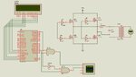
Here is the circuit diagram of the inverter i made in Proteus..without connecting the output of AND gates to the MOSFET's gate terminals
And also the simulation result of the circuit..in Proteus CRO..
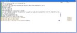
But when i connect the output of the two and gates to the gate terminals of the H bridge, the simulation stops and i am getting a window like this..
I am trying to make a sine wave inverter. But i am facing a lot of troubles. At the first time i feel it might be easy to generate the sine wave using the controller because i studied that using a low pass filter at the output of the high frequency output of the controller then the square wave will become sine wave. I used a LC low pass filter. But before that i applied the square wave pulses from the controller to an H bridge using Mosfets. And i fed the output of the H bridge to LC low pass filter. But i didnt get the sine wave output. I am giving my code here. I am not sure that my program is right or wrong. But i wrote the program using my own idea. Somebody please help me to correct this..
Here is the circuit diagram of the inverter i made in Proteus..without connecting the output of AND gates to the MOSFET's gate terminals
And also the simulation result of the circuit..in Proteus CRO..
But when i connect the output of the two and gates to the gate terminals of the H bridge, the simulation stops and i am getting a window like this..
![Sine Wave Inverter[after connecting with MOSFETS].JPG](/data/attachments/33/33805-c6e387812b075cbf5a8c66b67c32f542.jpg)