Continue to Site

Welcome to EDAboard.com

Welcome to our site! EDAboard.com is an international Electronics Discussion Forum focused on EDA software, circuits, schematics, books, theory, papers, asic, pld, 8051, DSP, Network, RF, Analog Design, PCB, Service Manuals... and a whole lot more! To participate you need to register. Registration is free. Click here to register now.

Generating DTMF with mcu using 2 output pins

Status
Not open for further replies.

neazoi

Advanced Member level 6
Joined
Jan 5, 2008
Messages
4,119
Helped
13
Reputation
26
Reaction score
15
Trophy points
1,318
Location
Greece
Activity points
36,918
Hi I have an MCU (atmega644p) and I want to generate DTMF tones using it.
I can use only two pins for that, so external resistor ladder DA converters are not an option.

I could generate each of the two tones for each DTMF key by setting the pins high and low at specific time intervals. However this would generate square waves.

So I wonder, how tolerant are telephone companies in the purity of the DTMF tones?
 

If you can generate PWM you can produce both tones as a composite waveform on one pin.

Telco DTMF levels are usually specified to be > -40dB for guaranteed operation so if you start at MCU square wave levels there is plenty of scope to add a passive filter which will 'round off' the waveform making it look nearer a sine. Note that there should be a difference in the two tone levels (aka "twist") but in practice it isn't necessary. Trying to pass DTMF square waves through a passband of ~300Hz to 3.5KHz wouldn't be feasible anyway.

Brian.

What is the frequency accuracy required in the tones ?
A simple way to convert PWM to sine? (I am not sure if the atmega644 has a PWM feature)
 

A frequency difference of 1 percent is probably close enough.
From B to C on the musical scale is 6 percent. That's wide enough to be distinguished by a narrow bandpass filter.

- - - Updated - - -

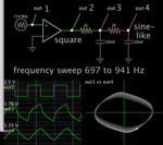
Two stages of RC low-pass filters are sufficient to shape a square wave into sine-like. (Frequency of dtmf rows is 697 to 941 Hz.)

sine-like from square waves RC low pass filters sweep 697-941 Hz DTMF.png

The lissajous figure compares the final waveform to the original sine. Notice it is almost circular, meaning they almost match. The sharp corners of the incoming square wave are filtered out. If desired, add another RC stage, although it would attenuate the signal further.

Only the RC networks are needed once you have a bipolar AC square wave. I guess your MCU makes 5v DC pulses, so you might want a DC blocking capacitor, then 1 or 2 or 3 RC filter stages.
For the dtmf columns (1209-1477 Hz), make a similar filter, but with reduced C values. Attach it to the other MCU output.
 
  • Like
Reactions: neazoi

    neazoi

    Points: 2
    Helpful Answer Positive Rating
Standard DTMF decoders use switched capacitor filters to separate the high and low group tones then coincidence detectors to decide which tone it is. They then use a timing circuit to ensure at least 40mS of that tone is present before signalling it to the outside world. The frequencies should be as accurate as possible but generally 1% is allowable.

If you can do it with PWM (I don't use ATMega devices normally) use a spreadsheet to calculate the sum of the composite signals for each digit then store them in a table so the samples can be read back sequentially. Much the same as generating sine waves with PWM but generating the DTMF tone instead.

You might find these interesting:
https://ww1.microchip.com/downloads/en/AppNotes/doc1982.pdf

https://github.com/antonmeyer/ArduinoDTMF

Brian.
 
  • Like
Reactions: neazoi

    neazoi

    Points: 2
    Helpful Answer Positive Rating
A frequency difference of 1 percent is probably close enough.
From B to C on the musical scale is 6 percent. That's wide enough to be distinguished by a narrow bandpass filter.

- - - Updated - - -

Two stages of RC low-pass filters are sufficient to shape a square wave into sine-like. (Frequency of dtmf rows is 697 to 941 Hz.)

View attachment 152668

The lissajous figure compares the final waveform to the original sine. Notice it is almost circular, meaning they almost match. The sharp corners of the incoming square wave are filtered out. If desired, add another RC stage, although it would attenuate the signal further.

Only the RC networks are needed once you have a bipolar AC square wave. I guess your MCU makes 5v DC pulses, so you might want a DC blocking capacitor, then 1 or 2 or 3 RC filter stages.
For the dtmf columns (1209-1477 Hz), make a similar filter, but with reduced C values. Attach it to the other MCU output.


Thank you very much for the useful info!
If you are aware of any MCU based fsk (1200 baud) modem please let me know. I have seen only 1-2 on the net
http://www.qsl.net/lz0icp/afsk1200.htm
http://www.vfx.hu/proj/fskmodem/fskmodem_eng.html

Some time in the past I found a modem which had also some AT commands, but I cannot find this link now. I think It used a single PIC MCU
 

Status
Not open for further replies.

Similar threads

Part and Inventory Search

Welcome to EDABoard.com

Sponsor

Back
Top