Continue to Site

Welcome to EDAboard.com

Welcome to our site! EDAboard.com is an international Electronics Discussion Forum focused on EDA software, circuits, schematics, books, theory, papers, asic, pld, 8051, DSP, Network, RF, Analog Design, PCB, Service Manuals... and a whole lot more! To participate you need to register. Registration is free. Click here to register now.

Generate a single-shot pulse from low voltage/current source

Status
Not open for further replies.

allsey87

Member level 4
Member level 4
Joined
Sep 27, 2010
Messages
70
Helped
17
Reputation
34
Reaction score
17
Trophy points
1,288
Visit site
Activity points
1,902
Hi All,

I need to generate a pulse about 250ms to 500ms wide at 24V. The application is to temporarily disable a magnetic field using a coil - the expected current at 24V is 500mA so we are talking about 12W.

The challenge is I need to run this from 3.3V supply without browning out the micro sharing the same supply, so I'm limited to drawing around 200mA from this supply (0.66W).

So I can come to a couple conclusions here, I need to 1/ step up my voltage, 2/ limit the downstream current draw to 200mA while charging a capacitor and 3/ discharge that capacitor using a 3.3V signal from the micro, while maintaining the 24V pulse for at least 250ms.

The final solution will go on a PCB and I'm looking for a fully/partially integrated solution to reduce the BOM as much as possible.

Any thoughts?
 

How often do you need to generate this 24V, 500mA, 250-500ms pulse (pulse frequency)?
That will determine whether the 200mA from the 3.3V supply is sufficient to do what you want.
 

If you intend to switch inductive load ( as I suppose have understood ), must take some additional precautions. If possible, put more details concerning to application.


+++
 

Hi andre_teprom and crutschow,

Thanks for the responses and questions. The pulse only needs to be generated about once a minute, so we have plenty of time to charge up a capacitor I believe.

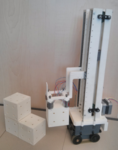
The application is for a mobile robot that can move blocks around. These blocks contain magnets and attach to the electro-permanent magnets on the robot. When the coil the electro-permanent magnet is activated, the magnetism is cancelled out and the block falls free due to the separation distance and gravity.

Here is a picture of what we are designing to get a better perspective:

bmanip-act.png

I'm currently working on a PCB to control the upper part of the robot, and I'm a little bit stuck on what combinations of circuits I need to use to achieve this pulse, or whether a fully or partially integrated solution already exists (to reduce the BOM).

Thanks in advance for any suggestions!

- - - Updated - - -

Information about the magnets can be found on this page [link]. We are using type code SE2.
 

You could use some low quiescent current step up converters as NCP1406 to get 24V, then use a resistor to limit the 24V current to 10-15mA (which will result in 100mA current from 3V) and then put a capacitor 500-1000uF after the resistor to store the 24V energy. When you connect something to the capacitor it could bring you currents even bigger than 0.5A.

In this way the maximum current from 3.3V will never exceed 100mA but you'll be able to sink from 24V currents bigger than 500mA (for short period of time).

Luben
 

Hi Guys,

yep, a step up is definitely a component of this circuit. What I'm trying to consider is the following:

1. Does a partially integrated solution exist? I have seen some ICs that are designed for generating a pulse to power a set of LEDs to be used in flash photography. The current-voltage ratings come close, but I haven't found exactly what I need yet. Also, would there be any issues arising from using this type of IC with an inductive load?

2. Given a partially integrated solution doesn't exist, then we need to use a step up from 3.3V to 24V. The question is whether to place the capacitor on the input or the output of the step up. You can get some super capacitors off Digikey, but the maximum voltage these go up to is around 4-5V so placing one of these on the input would be an option. The issue here is that the voltage during discharge of any capacitor is exponential, and would very quickly drop under the V_in cut off value of most step ups that I have seen. Placing a capacitor at the output of the step up of around 1-6F is also an alternative, however we have the same issue with the exponential drop off of the capacitor voltage, and it is a requirement that the voltage level stay at 24V at least for 250ms...
 

How about using a small rechargeable battery rather than a capacitor to store the 24V energy. That way the output voltage would stay basically constant during the pulse output. The batteries would slowly charge during the time between pulses. You could use a battery pack such as this.
 

The OP didn't mention it at all, but I guess besides reduced BOM he also imagines a small form factor. This may be a problem.

Identifying a suitable energy storage option for the projected 3 to 6 Ws (plus losses) seems to be the obvious first design step.
 

Status
Not open for further replies.

Similar threads

Part and Inventory Search

Welcome to EDABoard.com

Sponsor

Back
Top