Continue to Site

Welcome to EDAboard.com

Welcome to our site! EDAboard.com is an international Electronics Discussion Forum focused on EDA software, circuits, schematics, books, theory, papers, asic, pld, 8051, DSP, Network, RF, Analog Design, PCB, Service Manuals... and a whole lot more! To participate you need to register. Registration is free. Click here to register now.

general circuit for SAR ADC

Status
Not open for further replies.

michcfr

Advanced Member level 4
Joined
Mar 7, 2012
Messages
106
Helped
0
Reputation
0
Reaction score
0
Trophy points
1,296
Activity points
2,011
Hello,
I need to connect an analog sensor to a MCU SAR ADC input. The tricky point is I want to design a generic circuit that can adapt to:
-various types of analog sensor, not known in advance
-various type of MCU (not known in advance) with 12bits resolution SAR SAR ADC

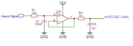
To cover the more general solution, I think to use a buffer opamp like in the attached schematic. So my questions are:
1)Is it a viable schematic regarding my requirements?
2)if yes:
-R1C1: necessary? correct values?
-RXCX: necessary? typical values?
-suggestion for the op-amp(U1A)?

Fell free to ask questions if it is not clear to you. Thx


Regards,
Michel
 

Attachments

  • op-amp-buffer.png
    op-amp-buffer.png
    7 KB · Views: 147

The better MCUs with SAR have a differential front end, and programmable
G diff amp in the input path. Component matching will control the CMR
the SAR has to deal with.

The LPF filters in your schematic limit BW and noise, so need dependent on application.

OpAmp should be a RRIO if possible, tons of choices on manufacturers website you can
'filter to to select. TI, Analog Devices....


Regards, Dana.
 

Necessary information to design the circuit:
- sensor output impedance
- sensor signal change rate respectively bandwidth
- ADC input current and maximal source impedance for full accuracy

Depending on the parameters, a buffer amplifier isn't necessarily required
 

Hi,
-various types of analog sensor, not known in advance
-various type of MCU (not known in advance) with 12bits resolution SAR SAR ADC
"not known in advance" means there is no clear requirement.

When I design a circuit, then I first decide the requirements.
So you try to design a "most versatile" circuit. While this is a good idea -- it it hard to solve.

--> I strogly recommend to define your own requirements.

***

To your circuit.
Where do you see the benefit in using your OPAMP circuit?
I start with the drawbacks:
* increased supply current
* introduces noise
* introduces offset and offset drift
* introduces nonlinearities
* you need a "unity gain stable OPAMP" otherwise you risk oscillation
* output can not go to zero (assuming a VCC / GND supplied OPAMP)
* output can not go to VCC

Back to the benefits:
* higher input impedance:
but this get´s killed by the relatively huge input capacitor at the input. Thus the improvement is just at very low frequencies.
If you have a high impedance sensor, then you get an unknown cut off frequency. but "unknown" is no benefit in my eyes.
But if you have a low impedance sensor, then omit the OPAMP (maybe just use the 10k and 100n in front of the ADC) while improving overall performance (see drawbacks). Many ADCs are happy with 10k input impedance.
* honestly I don´t see any other benefit of the OPAMP here.

Don´t get me wrong: I often use OPAMPs, also in front of an ADC. When correctly adjusted to the sensor and the ADC then they bring benefits. But you have to be aware of the drawbacks, too ... and decide wheter / in which case they improve the performance.

****
Opamp circuits in front of ADCs are good:
* for gain setting
* to add DC offset
* to act as anti aliasing filter
* to act as differential to single ended converters
* to act as impedance converter

But they will never improve
* DC performance
* noise performance
* distortion
(In best case they can help to keep noise and distortion low)

Klaus
 

Some designs use a SAR because they are trying to achieve simultaneous sampling, such as in
multiphase systems or multiple sensors where one needs specific values at a point in time.

Some MCUs have this single chip capability. The S/H can operate either in S/H mode or Track and Hold mode.-

1643288501511.png


Regards, Dana.
 

Attachments

  • 1643286741942.png
    1643286741942.png
    23.5 KB · Views: 104
Last edited:

Hello
Thank you for your feedbacks.

@FvM : thank you for your tips. I'll gather these info from the list of sensors I plan to use, and I brb to you.

@KlausST : thank you for your response and explanations
"not known in advance" (or if you prefer "most versatile") are my own requirements.
If it is achievable or not, or if I have to specify additional constraints/requirements due to engineering feasability is another problem. And this is the purpose of my message and my questioning.

@danadakk : I'm very interested by you second message. This is the kind of design I want to do but without the Clock_1, the sensor input is selected directly by the microcontroler. Something I don't catch is why the Sample&Hold block is duplicated? why not place a single Sample&Hold block between the AMux_1 and the ADC_SAR_1? since the ADC is done one at a time?
Do you have more doc or link about this kind of circuit?


As general message, I understand that the buffer amplifier isn't necessarily required.


Regards,
Michel
"Normally" you would just use one S/H. But point was to do simultaneous sampling,
hence the need to clock multiple Synchronously.

Clock_1 is an internal clock, you can clock the S/Hs with external or logical derived clocks.

Here is a representative picture of all the resources on the PSOC 5LP, attached is a catalog
of the internal resources. There are multiple copies of each part should user choose, but
overall limits, eg. size of fabric used for some of the digital parts and custom parts. Same
with OpAmps, 4......

1643326194001.jpeg


There are a lot of videos on Cypress/Infineon website. You drag and drop components (internal resources, onto design canvas, dbl click to config and gain access to APIs associated with each
component, and wire up internally. You can do anything from codeless designs to more normal
coded designs. Create your own internal components using schematic capture of the internal
components and/or use verilog. Community has done additional components like DDS, 74HC
logic type parts, PLDs.......

Tons of project resources both in the IDE, PSOC Creator, free and its compiler free.


Regards, Dana.
 
Last edited:

If you want close to 11 bit accuracy out of a 12 bit machine
your op amp had better contribute no offset or gain error.

RRIO amplifiers often lose gain and pick up offset as you
approach the rails. This may compromise linearity / accuracy.
An op amp with wider rails than the MCU could be a better
option for accuracy (not cost, area unless those rails are
"freebies" (like a +/-15V system with +/-10V signal range,
ships those supplies all over and one more "client" means
nothing much). In a 5V-only system you might still like a
5V-to-split-12V, split-15 DC-DC module (which might also
allow you to deal better with sensors that produce less than
zero or more than 5V).
 

Hi,

Using Opamps with higher supply voltage than the MCU, or negative means risk of overdrive the MCU input pin .. and damage.

I still miss the information why you think the Opamp brings any benefit.
An Opamp does not make the input more flexible or more versatile.

If you want to build something fir flexibke use,
* then add a jumper so you can use the ADC input directly or via the Opamp
* add (pads for) at least 4 resistors: 2 at non unverting input, one at inverting input, one feedback resistor.
Then you are free to populate resistors and or capacitors to desingn
* inverting amplifier
* non inverting amplifier
* differential input amplifier
* add offset
* set gain as desired
* build filters
* ...

Or use a "programmable signal conditioning IC", that can do all the same but configured via an MCU instead of individual soldering.

Klaus
 

Status
Not open for further replies.

Similar threads

Part and Inventory Search

Welcome to EDABoard.com

Sponsor

Back
Top