JohnDoe19700101
Newbie level 2
Hello!,
I have built a geiger counter using the SI-3BG russian tube with the following data:
380-460VDC operation voltage so: i have tuned mine to 420V since i have come to understand that you should be in the middle of the operation plateu.
0,015-0,02mkA i guess that is 15-20µA.
:
Working Range of Dose Power 300R/h
Working Voltage 380-460V
Working Current 0,015-0,02 mA
Plateau Length/ Inclination 80V/0,25%/V
Sensitivity to Gamma Radiation 188 - 235 Pulses/s/R/h
Own Background 0,2 Pulses/s
Working Temperature Range -50 +60 С
Length 55mm
Diameter 10mm
:
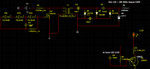
However i cant seem to get any readings from it i have it connected to the 420V on the annode and 470k to GND on the cathode hopeing to detect someting on my DVM over the 470k.
here is a conceptual shematic of my design in PNG.
I accually have 7 villard cascade steps with 100nF caps and 1N914 Diodes.
And currently you can ignore the led/speaker step in the corner, its not done yet.
I removed the 21Mohm resistor since it gave me 20µA trought but gave a wierd Voltage drop to exactly 137V between GND and annode. Could have been that the DVM is loading the circuit..
Can anyone tell me why I am supposed to have it in the middle of the Voltage platue!?
Maybe link some resources about the physics of the GM tube.
And is my GM tube data too bad to get background radiation readings?
Seems like the annode is having 0,0µA current constantly like i get no disharge...
Cheers JD.
I have built a geiger counter using the SI-3BG russian tube with the following data:
380-460VDC operation voltage so: i have tuned mine to 420V since i have come to understand that you should be in the middle of the operation plateu.
0,015-0,02mkA i guess that is 15-20µA.
:
Working Range of Dose Power 300R/h
Working Voltage 380-460V
Working Current 0,015-0,02 mA
Plateau Length/ Inclination 80V/0,25%/V
Sensitivity to Gamma Radiation 188 - 235 Pulses/s/R/h
Own Background 0,2 Pulses/s
Working Temperature Range -50 +60 С
Length 55mm
Diameter 10mm
:
However i cant seem to get any readings from it i have it connected to the 420V on the annode and 470k to GND on the cathode hopeing to detect someting on my DVM over the 470k.
here is a conceptual shematic of my design in PNG.
I accually have 7 villard cascade steps with 100nF caps and 1N914 Diodes.
And currently you can ignore the led/speaker step in the corner, its not done yet.
I removed the 21Mohm resistor since it gave me 20µA trought but gave a wierd Voltage drop to exactly 137V between GND and annode. Could have been that the DVM is loading the circuit..
Can anyone tell me why I am supposed to have it in the middle of the Voltage platue!?
Maybe link some resources about the physics of the GM tube.
And is my GM tube data too bad to get background radiation readings?
Seems like the annode is having 0,0µA current constantly like i get no disharge...
Cheers JD.