Continue to Site

Welcome to EDAboard.com

Welcome to our site! EDAboard.com is an international Electronics Discussion Forum focused on EDA software, circuits, schematics, books, theory, papers, asic, pld, 8051, DSP, Network, RF, Analog Design, PCB, Service Manuals... and a whole lot more! To participate you need to register. Registration is free. Click here to register now.

Gate driver IR2106-Convergence problem Orcad 16.2 Pspice

Status
Not open for further replies.

gatedriver

Junior Member level 1
Joined
Jul 4, 2011
Messages
17
Helped
0
Reputation
0
Reaction score
0
Trophy points
1,281
Activity points
1,455
Hi everyone,

I am doing simulation gate driver by Orcad - pspice. But i met so many problem with this device.

- gate driver model: IR2106 (downloaded from IR website)
- PWM input are square waves (1kHz) from 0-3.3V
- It also included delay time 0.4us for dead time
- the type of diode is fast reverse recovery
When I simulated this gate drive sepearate, The ouput signals on HO, LO pins are ok.

But when I applied power circuit (half bridge), the convergence problem always happen.

The problem report usually mention the errors relate to some diodes of of IR2106 and switches.

My silmulation settling:
TSTOP 2.5ms
Maximum step 0.1u (some time I increase to 12u, but the same result)
RELTOL 0.1; VNTOL 0.1; ABSTOL 1u; CHGTOL 0.01N; ITL4 150; ITL1 500;

I do this simulation during two weeks, but the result is always convergence problem.
Could anyone please help me to solve this problem? gatedrive2.gifgatedrive1.gif
Thank you very much!
 

Attachments

  • Question_IR2106.doc
    31 KB · Views: 153
Last edited:

Please check the Gate connection at High Side IGBT, Z5. I suspect VS pin should be directly connected to Emitter. Also can you try removing the Gate driver IC and try directly driving the gates from pulse sources? This would help isolate the problem area. I assume sources are set up correctly and they are not leading to cross conduction.

Can you share the complete schematic or netlist with models?
 
Hi alexan_e and atrianpathi,
Thank for your help.

I already downloaded your related documents about convergence problem. But, unfortunately, I can not solve my problem.

Could your please see my problem again with more detail below.

I change some detail in my circuit,

I used delay switches (1ms) for operating gate driver first.

Then the lower IGBT will turn on.

The convergence problem happen at the time the higher IGBT start turning on, that means DC voltage source (100V) applied the circuit.

I do not know why?

Please give me some hints. Thanks a lotgatedrive2106_question.gif

thanks for your help.

and this is my netlist

* source IR2106_FI
V_Vtri1 N42345 0
+PULSE 0 3.3 0 1n 1n {(1/{2*{1kHz}}-2n)} {1/1kHz}
X_U3 N55458 N45885 Sw_tClose PARAMS: tClose=1ms ttran=1u Rclosed=0.01
+ Ropen=1Meg
R_R2 N42139 N42127 18 TC=0,0
C_C1 N42241 0 1u
X_Z1 N44942 N52963 N45885 IRGP30B120KDE
V_V1 N42241 0 15Vdc
R_R6 N44396 0 2 TC=0,0
V_Vtri4 N42335 0
+PULSE 0 3.3 {3/(6*{1kHz})+0.4u} 1n 1n {(1/{2*{1kHz}}-0.8002u)} {1/1kHz}
R_R3 N42393 N55458 5 TC=0,0
X_D1 N42241 N42359 murs260t3/ON
C_C3 N44942 0 500u
X_D2 N42001 N420431 murs260t3/ON
R_R4 N42009 N420431 3 TC=0,0
X_U4 N42127 N57780 Sw_tClose PARAMS: tClose=1ms ttran=1u Rclosed=0.01
+ Ropen=1Meg
X_Z2 N45885 N57780 0 IRGP30B120KDE
X_U2 N42001 N52963 Sw_tClose PARAMS: tClose=1ms ttran=1u Rclosed=0.01
+ Ropen=1Meg
X_D3 N42127 N420911 murs260t3/ON
R_R5 N42139 N420911 3 TC=0,0
V_V2 N44942 0 100Vdc
C_C2 N42359 N42393 1u
L_L1 N45885 N44396 10mH
X_U1 N42241 N42335 N42345 0 N42359 N42009 N42393 N42139 IR2106 PARAMS:
+ CDELAY=50N RDELAY=50 T1=-40 T2=25 T3=125 V1=10 V2=15 V3=20 TOFFT1=200N
+ TOFFT2=200N TOFFT3=200N TOFFV1=200N TOFFV2=200N TOFFV3=200N TONT1=210N
+ TONT2=210N TONT3=210N TONV1=210N TONV2=210N TONV3=210N
R_R1 N42009 N42001 18 TC=0,0
 

I have posted the link because they contain the only way I know that can solve problems but you have already done that.

Increase Iteration limit (ITL)

and decrease the accuracy
ABSTOL is the absolute current tolerance (default value is 1pA)
VNTOL is the absolute voltage tolerance (default value is 1uV)
RELTOL is the relative tolerance (default value is 0.001 = 0.1%)

Alex
 

I already did change these parameters,
but the convergence problem still happened at the time DC link voltage (Vdc = 100V) is applied.


How can I do?
 

i solved this a long time ago.. by memory, i believe it had something to do with the model file's ground reference. it uses node '0' as the ground which is SYSTEM ground. you have to change this to some variable name (i used "ref") and then apply your floating power supply's reference to this pin.
 
Thanks

i used ground type 0/CAPSYM and my circuit can run.

But It can run only with TSTOP = 2.5ms, and the maximum step =10u

When I change maximum step value the convergence problem still happen.

How can I setup this value correctly?

Now, I want to increase the simulation time to 5ms, how can I set maximum step value?

I already tried some values of maximum step, but convergence problem happened.
 

* source IR2106_FI
R_R8 0 N42241 1G TC=0,0
V_Vtri1 N42345 0
+PULSE 0 3.3 0 1n 1n {(1/{2*{1kHz}}-2n)} {1/1kHz}
X_U3 N55458 VS Sw_tClose PARAMS: tClose=1ms ttran=1u Rclosed=0.01
+ Ropen=1Meg
R_R2 N42139 N42127 18 TC=0,0
C_C1 N42241 0 1u
X_Z1 N44942 HO1 VS IRGP30B120KDE
R_R9 0 N44942 1G TC=0,0
V_V1 N42241 0 15Vdc
R_R6 N44396 0 2 TC=0,0
V_Vtri4 N42335 0
+PULSE 0 3.3 {3/(6*{1kHz})+0.4u} 1n 1n {(1/{2*{1kHz}}-0.8002u)} {1/1kHz}
R_R3 N42393 N55458 5 TC=0,0
X_D1 N69252 N42359 murs260t3/ON
R_R10 N42241 N69252 0.01 TC=0,0
C_C3 N44942 0 500u
X_D2 N42001 N420431 murs260t3/ON
R_R7 N42393 N42359 1G TC=0,0
R_R4 N42009 N420431 3 TC=0,0
X_U4 N42127 LO1 Sw_tClose PARAMS: tClose=1ms ttran=1u Rclosed=0.01
+ Ropen=1Meg
X_Z2 VS LO1 0 IRGP30B120KDE
X_U2 N42001 HO1 Sw_tClose PARAMS: tClose=1ms ttran=1u Rclosed=0.01
+ Ropen=1Meg
X_D3 N42127 N420911 murs260t3/ON
R_R5 N42139 N420911 3 TC=0,0
V_V2 N44942 0 100Vdc
C_C2 N42359 N42393 1u
L_L1 VS N44396 10mH
X_U1 N42241 N42335 N42345 0 N42359 N42009 N42393 N42139 IR2106 PARAMS:
+ CDELAY=50N RDELAY=50 T1=-40 T2=25 T3=125 V1=10 V2=15 V3=20 TOFFT1=200N
+ TOFFT2=200N TOFFT3=200N TOFFV1=200N TOFFV2=200N TOFFV3=200N TONT1=210N
+ TONT2=210N TONT3=210N TONV1=210N TONV2=210N TONV3=210N
R_R1 N42009 N42001 18 TC=0,0

This is my netlist

Why i can not extend my simulation time or change the maximum step?

any changing these parameters also lead to convergence problem.

Please give me some hints
 

Can you upload and share the schematic? It's lot easier to manipulate schematic in comparison to text based netlist?
 

Hi, i saw many files which were created from program. So I copy all of this. Please noted me if you cannot open this model

In this circuit, there are some differences from above circuit. In this case, I use full bridge circuit because I afraid of the effect of load, so i choose the R load.

The convergence problem also happened.

Thanks you for your help. I am waiting some hints from all of you.
 

Attachments

  • IR2106-FULLBRIDGE.rar
    60.9 KB · Views: 111

many things happen.
In some lucky time, I choosed TSTOP, and maximum step size : the system can run to 2.5ms

when I want to extent Tstop or adjust maximum step size: the convergence appear.

may be the time when two switch transfer, the current sharply increase, but i already try to avoid dead time


Why?.... many questions, many problems .... huhuhu
 

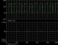
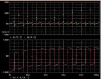
I think there is some problem with IR2106 models. try this model separately and check if you are getting the gate pulse at output of this(HO,Vs). At my end I am not getting any pulse at high side output of gate driver. If I remove this driver IC and directly drive the power circuit, everything seems to work fine.
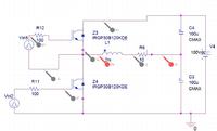
refer the results & circuit I am using below. I am circuit provided by you.
Hope this helps.

First image is output at IR2106
Second image is output of power circuit without IR2106. Top waveforms are IGBT currents and bottom one is voltage across load.
Third one is circuit used for second set of waveform.
 

Hi atripathi,

thanks you for your help.

But actually, I need to do simulate with Gate driver model. I think the circuit is ok but the problem came from the pspice program. (for example: this circuit can run at some specified TSTOP and maximum step, but with other values the convergence problem appear again, and then I can not the circuit with old parameters (TSTOP and maximum step)

My basic knowledge can not handle this problem and I will try more about this.

How can I identify my problem? I need some help from all of you.

Thanks a lot
 

I would recommend simulating the IR2106 model without any power circuit. You shall be able to get the pulses to drive power switches. In the model here High side gate pulses are missing. Refer the bottom waveform in first picture from my previous post. Check the same at your end. This could also be a reason for convergence error, hence I do not suspect PSpice here. Check at your end for pulses at IR2106 output, in healthy condition one should get voltage connected at HIN & LIN.
 

Status
Not open for further replies.

Similar threads

Part and Inventory Search

Welcome to EDABoard.com

Sponsor

Back
Top