Continue to Site

Welcome to EDAboard.com

Welcome to our site! EDAboard.com is an international Electronics Discussion Forum focused on EDA software, circuits, schematics, books, theory, papers, asic, pld, 8051, DSP, Network, RF, Analog Design, PCB, Service Manuals... and a whole lot more! To participate you need to register. Registration is free. Click here to register now.

Gain drift with INA111 Instrumentation Amplifier

Status
Not open for further replies.

emsensors

Junior Member level 3
Joined
Jul 16, 2011
Messages
29
Helped
0
Reputation
0
Reaction score
0
Trophy points
1,281
Location
Iowa
Activity points
1,563
Hi,

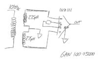
I am using a INA111 Instrumentation Amplifier with gain in the range 100 to 3000. The input consists of two fairly well matched coils symmetric about a driver operating at 10 kHz. The coils have an impedance of maybe 20 Ohms or so and 3 Ohms DC resistance. So, the setup is kind of like an LVDT. The coils are connected in such a way as to null when there is no 'displacement' - see figure. I am observing some gain drift with temperature and despite a lot of research I cannot find a good resource that will help me solve this problem. So, two questions... 1) Anybody got any suggestions as to how I could go about trimming this temperature coefficient of gain? 2) Anybody know of any good resources (print or online) that discusses temperature compensation in general or with an emphasis on op-amp circuits?

Many thanks!


How do you know that your signal source is not changing output with temperature?. Does your "displacement" change with temperature? What sort of level are you talking about? For really hi precision work (Dl < 1 X 10^ -6), all the components must be temperature cycled to relieve any inbuilt winding tension and the winding securely fixed.
Frank
 
Thanks for your reply. Well, my source signal does change with temperature but I am able to deal with that in a different way. The temp coefficient of gain in the instrumentation amplifier I have verified by heating and cooling the device. The effect is small and cannot be observed on a scope of the output. However, after detection and amplification it is large enough to be a problem.

Thanks.

- - - Updated - - -

Just to clarify - this is not a LVDT, it is a differential eddy-current sensor designed to measure the gap between the bottom of the sensor and a conducting plate.
 

Okay, I measured the AC voltage under ambient conditions and obtained a value of 168 mV. With a fixed gain of 1500 that means the input should be 112 uV. I then sprayed cooler aerosol on the chip and the output went up to 170 mV which corresponds to a gain of 1517. This represents a 1.13 % change in gain. Now, assuming the cooler spray reduced the chip temperature to 0 C from 20 C then that corresponds to a change of 0.06 % / C or 560 ppm / C. This seems very high - have I done something wrong?

Thanks!

Thanks for your reply. Well, my source signal does change with temperature but I am able to deal with that in a different way. The temp coefficient of gain in the instrumentation amplifier I have verified by heating and cooling the device. The effect is small and cannot be observed on a scope of the output. However, after detection and amplification it is large enough to be a problem.

Thanks.

- - - Updated - - -

Just to clarify - this is not a LVDT, it is a differential eddy-current sensor designed to measure the gap between the bottom of the sensor and a conducting plate.
 

So, put a thermsitor from the output to the inverting input of the instrumentation amplifier? With a temperature coefficient equal to what I observe? Will it affect the gain? How would I select a value and would this work for all gains or would it need to change if I altered the gain-setting resistor? I am still confused as to why the value of the gain temperature coefficient that I calculated is so high - much higher than values specified in the datasheet. Thanks for your help!

How about using a thermistor in the NFB path?
Frank
 

Now I'm thinking it might be drift in CMRR with temperature. I use the same IC in a different part of the circuit with just as much gain and it does not drift at all. The difference being that this second circuit is configures as a single-ended input, i.e. the other input to the INA111 is grounded. Any comments? Thanks!

- - - Updated - - -

Now I'm thinking it might be drift in CMRR with temperature. I use the same IC in a different part of the circuit with just as much gain and it does not drift at all. The difference being that this second circuit is configured as a single-ended input, i.e. the other input to the INA111 is grounded. Any comments? Thanks!
 

It sounds more like offset drifting to me, not gain. Also, be careful interpreting results with freezer sprays - they can go down to -50C and below and cause a lot of condensation. Some effects can actually be due to the moisture.

Keith
 
Last edited:
100 PPM/degC looks like worst case for the chip. Try changing the type of your Rg, as this has a major effect on the gain and your one might not be temperature stable!!
Frank
 
Would that affect ac performance? I am monitoring the signal after a bandpass filter and so assumed that offset drift was not a contributor - maybe I am wrong about this?

Also, thanks for the hint on freezer spray - makes perfect sense now you told me!

Thanks!

It sounds more like offset drifting to me, not gain. Also, be careful interpreting results with freezer sprays - they can go down to -50C and below and cause a lot of condensation. Some effects can actually be due to the moisture.

Keith

- - - Updated - - -

I'm using 25ppm resistors for the gain - heating and cooling these has almost no effect. Something else is going on here I just can't seem to figure it out!

100 PPM/degC looks like worst case for the chip. Try changing the type of your Rg, as this has a major effect on the gain and your one might not be temperature stable!!
Frank
 

If it is genuinely AC signals you are measuring then no, offset drift won't affect it (I didn't see any AC coupling or HPF/BPF in your schematic).

As mentioned by earlier posters, the TC of resistors and IC are important in precision circuits so could be your problem.

Keith
 

Status
Not open for further replies.

Part and Inventory Search

Welcome to EDABoard.com

Sponsor

Back
Top