Continue to Site

Welcome to EDAboard.com

Welcome to our site! EDAboard.com is an international Electronics Discussion Forum focused on EDA software, circuits, schematics, books, theory, papers, asic, pld, 8051, DSP, Network, RF, Analog Design, PCB, Service Manuals... and a whole lot more! To participate you need to register. Registration is free. Click here to register now.

Gain differences between HFSS simulation and test results

Status
Not open for further replies.

LTCC

Member level 1
Joined
Jun 20, 2007
Messages
34
Helped
0
Reputation
0
Reaction score
0
Trophy points
1,286
Activity points
1,523
Hi, everyone.
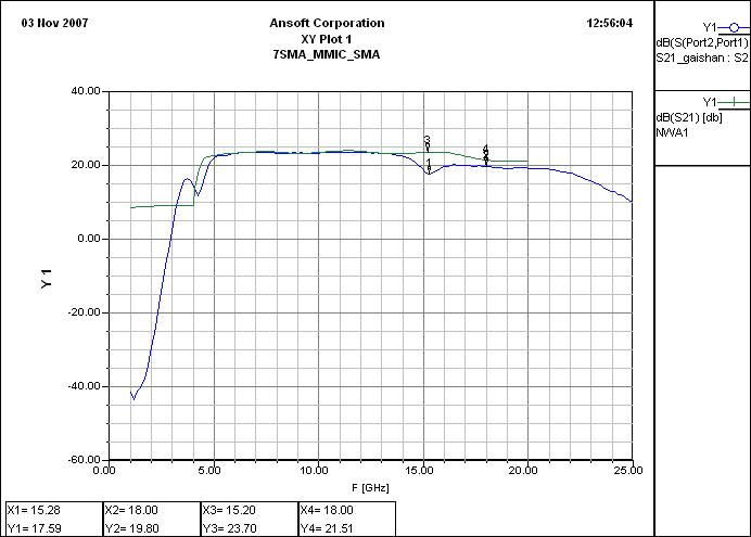
I have simulation a LNA in HFSS using Rogers5880 substrate, the following fig is the test result(in blue) vs the simulation result(in green). The two have a good agreement within 13.5Ghz, but after that they are quite different, especially in the frequency of 15.28Ghz(mark 1).

Can anyone give me some advices how this happen and how to minimize the difference?


how do you manage to simulate a transistor device (LNA) in HFSS?
 

Sorry, I didn't express myself clearly.

I've simulated the passive part(PCB) of the LNA,not the active circuit
 

you are measuring on a very large bandwidth. Is your Network calibrated correctly on the whole BW.
On the other side, I would prefer to redo a simulation around 15.28Ghz with some discrete points.
 

    LTCC

    Points: 2
    Helpful Answer Positive Rating
Thank you for eastern.
I also did a calibration from 14Ghz~19GHz,and the results turn out to be the same with the wider band.

I'll redo a simulation as you suggested.
 

why thanks, if the results are the same ?
 

Status
Not open for further replies.

Part and Inventory Search

Welcome to EDABoard.com

Sponsor

Back
Top