xxargs
Full Member level 4
yjkwon57 said:Hi, powersys.
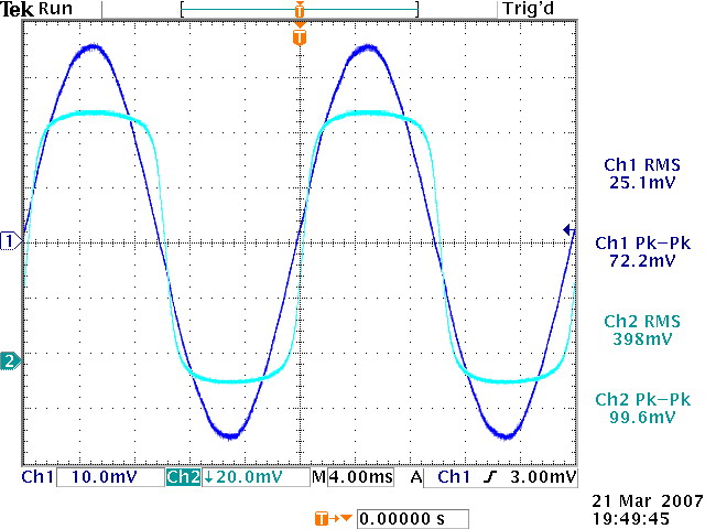
I looking figure 5 in beginning - is not so 'stupid' misstake as you measure in AC-input on your oscilloscope? - you have High pass filter-function on input in this case and with low frequency, voltage lower @ RC-function on your display if voltage spend longer time compare to your RC-constant on your input and this way make loop on your display.
Try measue with DC-coupling on oscillosope input and see if changes.