Continue to Site

Welcome to EDAboard.com

Welcome to our site! EDAboard.com is an international Electronics Discussion Forum focused on EDA software, circuits, schematics, books, theory, papers, asic, pld, 8051, DSP, Network, RF, Analog Design, PCB, Service Manuals... and a whole lot more! To participate you need to register. Registration is free. Click here to register now.

[SOLVED] Fully Differential Amplifier and output common-mode voltage

Status
Not open for further replies.

hannover90

Member level 4
Joined
Dec 8, 2009
Messages
70
Helped
0
Reputation
0
Reaction score
0
Trophy points
1,286
Location
Germany
Activity points
1,784
Hello all,

I have a problem to understand fully differential amplifiers and also their CMFB.

I learned from theory vout2-vout1=A*(vin2-vin1) and the gain (A) is infinite.

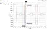
But I don't understand, how would be the output signals of a FD-Amp with supply voltages of -1.7 V and 1.7 V and an output common-mode voltage of 0.8 V regarding the input signals, as attached?

How high should be the gain?

.
 

Attachments

  • Input_Signals.jpg
    Input_Signals.jpg
    84.1 KB · Views: 178

The gain A is not infinite in reality it is just quite large. If you want to use it to monitor signals in the open loop for an amplifier you need to know the gain. When your input signal amplitude goes to 500mV (vin2-vin1) the output will go to A times 0.5V if the amplifier can support it in its output dynamic range. Usually the output will saturate even from very small input signals because of large gains. Also then you put in a step signal the output will initially slew up at the maximum slew rate of the amplifier and then settle to whatever maximum it can go to.
 
many thanks, aryajur.
Regarding your explanation, I drew the output signals with a gain of 26.
The outputs of the input signals of 50 mV and 500m V would be 26*50mV=1,3 V and 1.7 V, respectively, if the supply voltages are -1.7 V and 1.7 V with a output common mode of 0.8 V.
Input_Output_Signals.jpg
 
Last edited:

Yes going to the high side it may go up to 1.7V if the amplifier output can go that high. That is only a 0.9V swing. On the low side there is more room and if the amplifier output can go down to -0.5V then you can get the full swing on the low side for +/-50mv input
 

Many thanks.
I've already designed a FD-amp. The output signals swing between ca. -1.7 V and 1.7 V with an OCM of 0 V.
Now, with a designed CMFB, i am trying to set OCM at 0.8 V. In this case, vout should swing betwenn 0 V and ca.1.7 V, but unfortunately, it oszillates. Should I use frequncy compensation techniqe?
It seems i did something wrong!
First, i increase the signal swing betwenn 1.7 V and -1.7 V with FD-Amp, after that i decrease the signal swing between 0V and 1.7 V using CMFB!!!
For any comments, i would be thankful.
 
Last edited:

Its difficult to suggest solutions without looking at the circuit but anytime you have a feedback you have to make sure the loop is adequately compensated to be stable. Once you add Common Mode Feedback you need to make sure that it is stable and you may need to add compensation to it.
 
Status
Not open for further replies.

Part and Inventory Search

Welcome to EDABoard.com

Sponsor

Back
Top