Continue to Site
Follow along with the video below to see how to install our site as a web app on your home screen.
Note: This feature may not be available in some browsers.
")
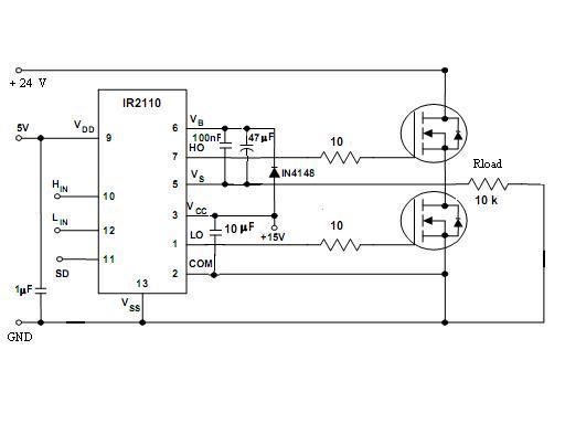

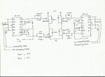
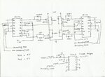
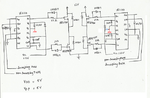
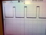
Dear Khushi,i am applying 5vp-p. and i m giving PWM from AVR microcontroller..and inverting PWM from schmitt trigger thru RC network at its input..i m attaching full schematic.plz tell me the mistakes in that. also tell me wats RCD u r talking about?????