Continue to Site

Welcome to EDAboard.com

Welcome to our site! EDAboard.com is an international Electronics Discussion Forum focused on EDA software, circuits, schematics, books, theory, papers, asic, pld, 8051, DSP, Network, RF, Analog Design, PCB, Service Manuals... and a whole lot more! To participate you need to register. Registration is free. Click here to register now.

Full Bridge driver with UCC28C43

Status
Not open for further replies.
Z

zenerbjt

Guest
Hi,
We wish to use UCC28C43 to drive a Full Bridge.
The attached shows it in LTspice.
Can you think of a more lower-component-count way of doing this?
 

Attachments

  • LT1243 as half bridge driver 2.txt
    5.5 KB · Views: 60
  • LT1243 as half bridge driver_2.jpg
    LT1243 as half bridge driver_2.jpg
    97.9 KB · Views: 95

To reduce component count, you'll use a dedicated push pull controller IC.
 
  • Like
Reactions: zenerbjt

    Z

    Points: 2
    Helpful Answer Positive Rating
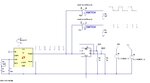
I suppose my schematic has a similar parts count. Same as your schematic mine has a D flip-flop performing clock-divide-by-2 (it's the easiest way I've seen to derive twin interleaved pulses). Duty cycle can be varied by a single adjustment to the incoming pulse train.

interleaved pulses adj duty cycle 1-49 pct (D flip-flop 2 NOR gates).png
 
  • Like
Reactions: zenerbjt

    Z

    Points: 2
    Helpful Answer Positive Rating
To reduce component count, you'll use a dedicated push pull controller IC.
Thanks, there are very few of these with a 1Volt Current sense pin which is good for CST connection.

It amazes me how few suitable push pull controllers exist for this.....there is LTC3723, but current sense threshold is very low and its very expensive.
 

Hi,

neither your schematic nor your description tells that you want current sense features.
Why now a different requirement?

Klaus
 
  • Like
Reactions: zenerbjt

    Z

    Points: 2
    Helpful Answer Positive Rating
The attached is the best so far, any improvements?
Full Bridge drivers are surprisingly hard to find with the versatility of the UCC28C43.

LTspice sim and pdf schem attached
 

Attachments

  • Full Bridge with UCC28C43 _A.TXT
    11.2 KB · Views: 105
  • Full Bridge with UCC28C43 _A.pdf
    34.8 KB · Views: 77

The attached is the best so far, any improvements?

You may observe in your simulation how a transformer (inductor) wants to continue conducting current when it's abruptly shut off. It may result in spikes, or even reverse current flow.
You may need to add a snubber network, or modify gating waveforms, try soft switching, etc.
 
  • Like
Reactions: zenerbjt

    Z

    Points: 2
    Helpful Answer Positive Rating
Status
Not open for further replies.

Similar threads

Part and Inventory Search

Welcome to EDABoard.com

Sponsor

Back
Top