ro0ter
Junior Member level 3
- Joined
- Jan 14, 2012
- Messages
- 26
- Helped
- 0
- Reputation
- 0
- Reaction score
- 0
- Trophy points
- 1,281
- Location
- Cluj, Romania
- Activity points
- 1,656
Hi everyone,
I was the proud owner of an Vellman DVM890F but unfortunately I can`t seem to accurately measure resistors anymore. Actually it can`t measure resistors at all, I get LOTS OF NOISE when doing so.
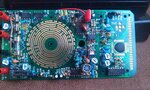
After a couple of days I decided to open it and I digged in for half an hour. I then found that the dial corresponding to 200MegaOhm is toasted (burnt). I hope I will be able to fix it with conductive silver paint.
The thing is that I could not see anything on the circuit board, I carefully inspected it but I was unable to detect any other anomalies. No broken resistors, no swollen capacitors, no exploded transistors.
Please help me fix my multimeter, I really need it.
Thank you
Here, some pictures with my multimeter`s board and closeup of the problem. This is the first time I opened it (if changing battery doesn`t count), the white areas are from the manufacturing process.


I was the proud owner of an Vellman DVM890F but unfortunately I can`t seem to accurately measure resistors anymore. Actually it can`t measure resistors at all, I get LOTS OF NOISE when doing so.
After a couple of days I decided to open it and I digged in for half an hour. I then found that the dial corresponding to 200MegaOhm is toasted (burnt). I hope I will be able to fix it with conductive silver paint.
The thing is that I could not see anything on the circuit board, I carefully inspected it but I was unable to detect any other anomalies. No broken resistors, no swollen capacitors, no exploded transistors.
Please help me fix my multimeter, I really need it.
Thank you
Here, some pictures with my multimeter`s board and closeup of the problem. This is the first time I opened it (if changing battery doesn`t count), the white areas are from the manufacturing process.