Continue to Site

Welcome to EDAboard.com

Welcome to our site! EDAboard.com is an international Electronics Discussion Forum focused on EDA software, circuits, schematics, books, theory, papers, asic, pld, 8051, DSP, Network, RF, Analog Design, PCB, Service Manuals... and a whole lot more! To participate you need to register. Registration is free. Click here to register now.

Frequent failure in Zener diode

Status
Not open for further replies.

srevish

Member level 2
Joined
Apr 23, 2013
Messages
48
Helped
0
Reputation
0
Reaction score
0
Trophy points
1,286
Activity points
1,661
Hi all,

I am using zener diode in my circuit, basically I am using this circuit as a water level sensor. Please find the attached file for the circuit diagram.

This 10V/3W zener is supplied 24Vdc, then the 10 V is drawn by a sensor of 120 ohms & by a resistor of 47 ohms.

Thus the current flowing zener diode is 0.083 A

R total = 120 + 47 = 167 ohms

I = 14/167 = 0.083A

Power on zener = 0.083 * 10 = 0.83 W

As per the derating, we have used 3 W zener diode.

But we are having frequent failure in the zener diode.

Can any one tell me what would be the root cause for this failure & is there is any way to stop it.

The sensor ( 120 ohms ) is off heating type, this will be in heated position always.
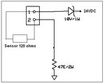


zener diode.jpg
 
Last edited by a moderator:

If everything is as you say, then there should be no excessive failure rate for the zeners. But if the 24VDC is really 28VDC and if the 120 Ohm sensor is sometimes looking like a 80 Ohm resistor, then the power in the zener would be 2.5 W. And if it is possible to short out pins 1 and 2 on the connector during installation, that would blow out the zener right away.
 

The zener is really rated at 3W with your heat sink?
Frank

Hi,

I did not use any heat sink for the zener diode,,, Is there is any type of heat sink available for it ?
 

If you look at the zener data sheet, it should tell you what the thermal resistance is (Junc-case), you can then work out the size of heat sink you need.
The 3 W rating will be the I X V of the diode, but the free air (un heatsinked) power could be .8W, but if mounted on a large heat sink so the diode can get rid of the heat then it will work forever at 3W.
Frank
 

To prevent damage to the Zener by an accidental short you can put it directly to ground, in series with the 47Ω resistor.

- - - Updated - - -

Hi,

I did not use any heat sink for the zener diode,,, Is there is any type of heat sink available for it ?
What is the diode case?
 

You have to give us more information. For instance, the zener's part number.

So...I'll assume a part number, the 1SMB5925B. (which is a SMB case).

If you read the datasheet carefully, you'll see that for the 3W power dissipation rating, there is a small note which reads verbatim:

Device mounted on FR-4 PCB; pad layout as shown on Diodes Inc. suggested pad layout document AP02001, which can be found on our website at
https://www.diodes.com.


Which you can find here: https://diodes.com/datasheets/ap02001.pdf
 

This 10V/3W zener is supplied 24Vdc, then the 10 V is drawn by a sensor of 120 ohms & by a resistor of 47 ohms.

Thus the current flowing zener diode is 0.083 A

R total = 120 + 47 = 167 ohms

I = 14/167 = 0.083A

Power on zener = 0.083 * 10 = 0.83 W

View attachment 111028

I may be wrong, but I think the calculations should be as follows:
Toatal voltage supplied to the circuit = 24 V
Total resistance in the circuit = 120 + 47 = 167 ohms
Total current in the circuit should be = V/R = 24/167 = 0.1437 A

If the voltage drop across the sensor is 10V, then the current trough the sensor, according to your data:
I = V/R = 10 /120 = 0.083 A

0.083 A is not equal to 0.1437 A, hence I feel, there is an error in your calculation/ measurement.

Also the zener datasheet is an important piece of information. Please share it.
 

" Toatal voltage supplied to the circuit = 24 V" right
"Total resistance in the circuit = 120 + 47 = 167 ohms" right
"Total current in the circuit should be = V/R = 24/167 = 0.1437 A" wrong, while 24V is applied, 10V of it is dropped across the zener, leaving only 14 V for the resistor and sensor.
Frank
 

Status
Not open for further replies.

Similar threads

Part and Inventory Search

Welcome to EDABoard.com

Sponsor

Back
Top