Continue to Site

Welcome to EDAboard.com

Welcome to our site! EDAboard.com is an international Electronics Discussion Forum focused on EDA software, circuits, schematics, books, theory, papers, asic, pld, 8051, DSP, Network, RF, Analog Design, PCB, Service Manuals... and a whole lot more! To participate you need to register. Registration is free. Click here to register now.

Frequency of FM transmitter not changing

Status
Not open for further replies.

fm101

Member level 5
Joined
Apr 13, 2020
Messages
81
Helped
1
Reputation
2
Reaction score
4
Trophy points
18
Activity points
591
Hello,
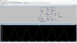
I have the following FM circuit, I build it but it is producing only 35MHz(I have build other working FM transmitters). I varied the trimmer capacitor, changed C3 to 18pF, compress expand the coil which is of 5 turns, changed to another coil with 7 turns etc but still cannot change the 35MHz to FM range(86-108MHz). What could be the problem? what can I do? looking for suggestions, thanks.

Fm-Tranmitter-300x213.jpg
 
Hi,

Where is this schematic from? Please give a link.

Also show your PCB layout / a photo of your design.
Proper operation of an RF circuit depends on the design of its circuit board. A schematic simply gives not enough information.


Klaus
 
The schematic doesn't even show a power supply bypass capacitor which is absolutely required. May be the circuit is oscillating at a parasitic resonance frequency defined by the batterry cable length or the antenna but without a layout photo further guesses are inappropriate. 2N2222 can definitely oscillate at FM frequency.
 

yes you need a capacitor across the battery.
And i believe you need a capacitor in parallel to R3, otherwise the gain and phase shift through your "common base" amplifier is unknown, as the base is not at RF ground.
 

Try decupling the base if TR1 and also the supply voltage as already suggested. The circuit will not work correctly without the base decoupled; the base needs to be RF grounded. It may be that there is a resonance there that is causing your problem. The circuit simulates OK in LTSPice.
 

Attachments

  • Osc Simulation.jpg
    Osc Simulation.jpg
    144.7 KB · Views: 113

I tried this circuit almost 50 years ago when I was a child. It's very bad design and the frequency shifts with the antennas position and temperature. Not a good starting point to learn the circuits.
The transistor was 2N2219A. paired with BC237B as an Audio Amplifier.
 
Hello,
This is follow up of the thread: https://www.edaboard.com/threads/frequency-of-fm-transmitter-not-changing.402694
which got closed with message Not open for further replies(I don't know why) and marked as solved(which is actually not).

I added power supply bypass capacitor 100nF and also added capacitor(10nF) parallel to R3 as suggested in previous thread but there is no improvement(no signal in FM band). Below is the schematic and picture. Why is this circuit not working? There are many one transistor FM circuits without the power supply bypass capacitor and many without the parallel base grounded capacitor and they are working. I have a working FM transmitter without these two capacitors. So there must be something else in this circuit.

2.jpg
3.jpg
 
Why is this circuit not working? There are many one transistor FM circuits without the power supply bypass capacitor and many without the parallel base grounded capacitor and they are working. I have a working FM transmitter without these two capacitors. So there must be something else in this circuit.
According to your own report in post #1, the circuit is working, but at 35 MHz, which sounds at least plausible due to the discussed circuit issues. Do you really want to further analyze the behaviour of bad circuit implementation instead of building it properly?
 

You are operating this 2N2222A at only 2.6 mA collector current. Its GBW pretty low
at that current, and this graph is typical, not worst case. So makes one wonder if you
have enough G at 100 Mhz to oscillate considering other circuit losses, like L Q, trans-
istor losses, etc...

1653734762556.png


Regards, Dana.
 
The coil instead of a whip antenna might reduce the frequency. Since the antenna connects directly to the tuned circuit then if anything moves towards the antenna it will add capacitance and reduce the frequency.

Since it is missing the pre-emphasis that all FM radio stations have then the de-emphasis on all FM radios will muffle the received sounds and make awful sounds like an AM radio.
 
Status
Not open for further replies.

Part and Inventory Search

Welcome to EDABoard.com

Sponsor

Back
Top