Continue to Site

Welcome to EDAboard.com

Welcome to our site! EDAboard.com is an international Electronics Discussion Forum focused on EDA software, circuits, schematics, books, theory, papers, asic, pld, 8051, DSP, Network, RF, Analog Design, PCB, Service Manuals... and a whole lot more! To participate you need to register. Registration is free. Click here to register now.

Frequency of Bode plot on X-axis

Status
Not open for further replies.

Mandar Joshi

Member level 2
Joined
Mar 4, 2015
Messages
50
Helped
0
Reputation
0
Reaction score
0
Trophy points
6
Activity points
445
I am using KDMG20008 speaker for my project. The datasheet of speaker shows graph of frequency in Hz vs. sound in dB (Bode plot). However I am not able to pick the frequency from the plot for which gain is maximum. Can anyone tell me how to calculate divisions on X-axis or directly values of X-axis? The graph is as shown in image below.

speaker graph.png

Also datasheet is attached for more detail. Sorry, if I have posted in wrong forum.
 

Attachments

  • Speaker.pdf
    426.3 KB · Views: 97

The X axis is logarithmic. It is not always easy to read.
600 Hz is the vertical line directly above the 'H' in Hz.
Starting at 2k, you can pick out 3k, 4k, etc.
10k is unmarked. 20k is marked at the right.

The highest point of the plot appears to be around 4.3 kHz.
 
The X axis is logarithmic. It is not always easy to read.

That is what I am not getting. Because according to the frequency on the graph I want to set PWM frequency, so that I will get good sound quality. I will try by 4.3KHz. I was assuming it near to 7KHz. But I will make changes & see the result.
 

The graph has no bearing on PWM requirements for quality. For this, PWM rate must much higher than signal freq. and for impedance control of power the carrier should be at least 10x the upper baseband signal.
 

Would you please explain? What should be the exact relationship between PWM frequency & wav file sampling frequency? As BradtheRad has said if gain is highest at 4.3KHz then what should be PWM frequency & wav file sample frequency?
 

Would you please explain? What should be the exact relationship between PWM frequency & wav file sampling frequency? As BradtheRad has said if gain is highest at 4.3KHz then what should be PWM frequency & wav file sample frequency?

What is the PWM frequency being used? If it is related to the power supply, it is not at all related. If you want to sample the .wav file, sample it at least twice the max frequency response you are planning to get...
 

I can get maximum PWM frequency of 31250Hz & I have decided to sample .wav file at 7812Hz or 8000Hz. Although it seems difficult from the graph above to get frequency for maximum gain.
 

PWM is a logic technique to control something. Most commonly, PWM is used to operate a switch- the switch is turned on at the leading edge of the pulse and turned off at the trailing edge. A transistor is the most common switch.

If you have a signal that you want to sample, the most common technique is to sample at equal intervals. The leading edge of the pulse in PWM are equally spaced and can be used for sample. But then I have not understood what you are trying to do. If you sample an analog sound signal at 8000 Hz, you will lose all high frequencies...

If you are sampling a .wav file, it is called resampling. Some extrapolation will be needed.
 

I just want to play .wav files using PWM & someone told me that if you play samples at frequency at which gain of speaker is maximum, you will get louder voice from speaker. Because for the speaker which I mentioned in #1 I am getting too low voice when I sample as I said in #7. i.e. sample at 7812Hz or 8000Hz and play it at 31250Hz. That is why I am looking for frequency for peak gain.
 

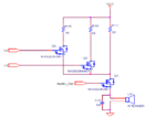
I am using following circuit for driving my speaker. Can someone guide me, what will happen if I use low drive circuit for speaker instead of high drive circuit?

Capture.PNG

As per above circuit, Vcc is 3.3V. Will it make any change if I change Vcc from 3.3V to 5V?

- - - Updated - - -

Please help me with this. MOSFET I have used is N-channel, enhancement trench MOSFET Part number is NX3020NAKT.
 

I do not understand how you are getting "audio out" from the gate connection. Gate is usually an input terminal and it also needs to be biased appropriately to be in the active region.

- - - Updated - - -

Are you trying to use the circuit as a mixer? What are V1 and V2 doing?
 

Look, Audio_Out goes to PWM o/p pin. V1 & V2 are connected to gpio of controller, which in turn used to ON & OFF MOSFETs. So that if put ON both V1 & V2, I will get highest volume.

Actually I used these two MOSFETs to change volume levels of speaker.
 

Look, Audio_Out goes to PWM o/p pin. V1 & V2 are connected to gpio of controller, which in turn used to ON & OFF MOSFETs. So that if put ON both V1 & V2, I will get highest volume.

Actually I used these two MOSFETs to change volume levels of speaker.

I see.

You mean "audio out" as "PWM in". You are just feeding the PWM signal to the speaker? It will be good to do some conditioning before you dump a series of pulses onto the speaker.

Switching on/off V1 /V2 just changes the source load on the transistor and it will change the gain. But this is not the right way- you need to fiddle with the gain. For example, if you are trying to use a high power speaker, this will waste too much of watts.

When you took the Bode plot of the speaker, did you keep the 1nF cap in parallel with the speaker? Although it may look small and innocent, it may have some significant effect on the resonance.
 

For now keep aside volume circuitry. My first concern is to get high audio intensity so that it is high enough to be audible. In that case what changes should I make in above circuit? Shall I change from high driver to low driver circuit for speaker?
 

Shall I change from high driver to low driver circuit for speaker?

Does it matter because the same current will flow through the speaker coils in either case. Your speaker is currently DC coupled and you should make it AC coupled by connecting with a capacitor in series (the other end of the speaker goes to the ground). The resistors should be comparable to the speaker coil resistance - not 36R but 10R (what is the VCC you are using)
 

I am using 3.3V as Vcc. I am also thinking of driving it with 5V at MOSFET.
 

I am using 3.3V as Vcc. I am also thinking of driving it with 5V at MOSFET.

Assuming a speaker coil resistance of 8R, max current in the coil would be around 180mA (ignoring the mosfet drop, which will be significant) which should be acceptable with a 10R for R17. You need to see the impedance of the mosfet at the proper operating point.
 

Speaker is of 8 Ohm only. Do you suggest that I should decrease value of R17 to 10 Ohm?

- - - Updated - - -

I have tried by changing it to 18 Ohm but no luck.

- - - Updated - - -

i.e. making values exactly half...18Ohm, 18Ohm, 9Ohm.
 

Just omit R17 and try. A small speaker is mostly resistance and series inductance. Your mosfet switch is not modulating properly.
 

Well...no resisor, I need to check first...but I can use 10 Ohm
 

Status
Not open for further replies.

Part and Inventory Search

Welcome to EDABoard.com

Sponsor

Back
Top