Continue to Site

Welcome to EDAboard.com

Welcome to our site! EDAboard.com is an international Electronics Discussion Forum focused on EDA software, circuits, schematics, books, theory, papers, asic, pld, 8051, DSP, Network, RF, Analog Design, PCB, Service Manuals... and a whole lot more! To participate you need to register. Registration is free. Click here to register now.

freq and stability analysis

Status
Not open for further replies.

bharathr87

Member level 1
Joined
Jan 27, 2009
Messages
34
Helped
0
Reputation
0
Reaction score
0
Trophy points
1,286
Activity points
1,482
why do we add an inductor and capacitor (LC ckt) in the feed back loop for freq and stability analysis for ex. as shown in this fig?
 

wait for a few seconds it will appear!!!
 

Hello Bharath..

Wht u have done is correct only..it's breaking the loop virtually and it's one of the way for stability analysis...

The easy way is connect the Vin- and Out put through iprobe (which can be found in analogLib)

and add stb analysis ( what ever frequency range u want.)

Vin+ is connected to a Ac Source with Ac magnitude =1 and DC voltage as VDD/2 i mean the common mode voltage.

u will get the loop gain,PM,GM,UGB.


Hope this could help You.

With Best Regards

ShaDy205
 

Thanks shady25.....i know that it is correct and it works...but can u help me figure out how the LC ckt is useful in doin the stability analysis....
 

Bharath..

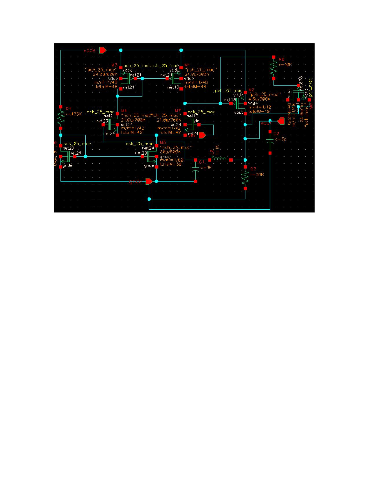
The actual way of doing with L and C is as follows.


Here the capacitor allows the ac signal and to flow through the OPAMP and evaluates the (gain & Phase response) stability response...the inductor blocks the AC signal coming from the Source. At the other end of the inductor u find the ac signal. from the Ac analysis find the Gain response from output to input and u will get the similar response as that of the stb analysis.

to get the Stability response keep high values of L and C...

Hope this could help u...

with Best Regards

ShaDy205
 

    bharathr87

    Points: 2
    Helpful Answer Positive Rating
Hi,
We only want the DC portion of the output to go to negative terminal, so that the op-amp is properly biased. So we use C and L to send only dc portion in feedback. And then we can apply the ac voltge seperatly on inegative terminal, to see the gain on the output.

Supreet
 

    bharathr87

    Points: 2
    Helpful Answer Positive Rating
Here is a short paper on a way to do it. Scroll to the end to see it.

Rich
 
Last edited by a moderator:

Status
Not open for further replies.

Similar threads

Part and Inventory Search

Welcome to EDABoard.com

Sponsor

Back
Top