Continue to Site

Welcome to EDAboard.com

Welcome to our site! EDAboard.com is an international Electronics Discussion Forum focused on EDA software, circuits, schematics, books, theory, papers, asic, pld, 8051, DSP, Network, RF, Analog Design, PCB, Service Manuals... and a whole lot more! To participate you need to register. Registration is free. Click here to register now.

FPGA VGA controller output "problem"

Status
Not open for further replies.

seyaleli

Newbie level 4
Joined
Dec 5, 2010
Messages
7
Helped
0
Reputation
0
Reaction score
0
Trophy points
1,281
Activity points
1,335
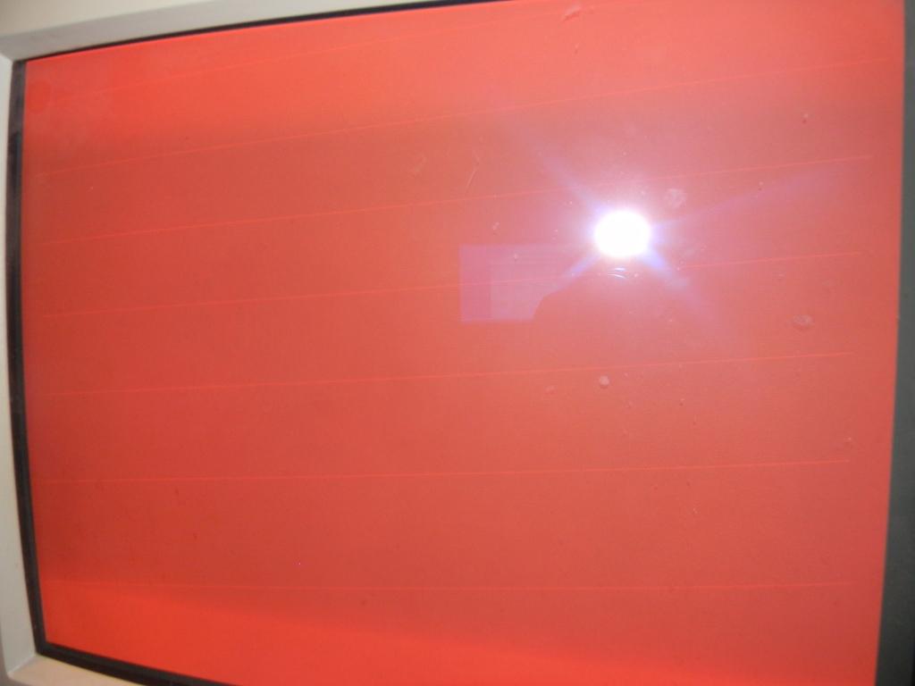
Hi guys. Iv'e written a simple vga controller (640x480) for a project of mine. I
synthesized the module on an altera DE-2 board and got good results (the
board uses a 4 bit DAC of each RGB). The problem is that I get kind of
"white" diagonal lines once every few raws. this resembles allot to the way
the crt "cannon" scans the frame, but I wasn't successful in making those
diagonal lines disappear. I'm attaching a picture for u to c...

Hope u can help.

Thanks in advance,

Eyal.


https://obrazki.elektroda.pl/14_1292269388.jpg
 

are you sure the sync is correct? Looks a bit like what you get on a CRT when you feed it a sync signal it doesn't like.
 

I'm pretty sure it is OK... the monitor reads 31.kHz horizontal, 60Hz vertical.

the vga timing data I get (I use altera's signal tap in order to verify it):

Hsync_data_width=24.6 u (micro) seconds.

Hsync_front_porch=1.92 u (micro) seconds.

Hsync_back_porch=0.68 u (micro) seconds.

Hsync_pulse_width=3.8 u (micro) seconds.

overall 32us for a horizontal cycle. could it be wrong? has anyone encountered

such a phenomena?

---------- Post added at 22:08 ---------- Previous post was at 22:07 ----------

sorry, Hsync_data_width=25.6 u (micro) seconds.
 

How about generating a checker board pattern and see if it remains stable.
 

I can try, but the image is stable and not flickering.
 

does your monitor tries to 'auto sync' to the VGA signal, or is it fixed.
 

Diagonal white lines sounds like missing frame blanking in the signal.
 

Exactly... got it fixed... somehow the blanking in was not on, so when the beam
returned to pixel (0,0) - the RGB value weren't on 0 volts. Thanks!
 

well if you feel generous today do post your code for the DE-2, it would be very interesting to see it!

Thanks
~B
 

Hello Guys,

I am trying to use the VGA display in a project using FPGA board. At the moment I am working on Basys2 FPGA kit from Digilent Inc, link www.digilentinc.com/Data/Products/BASYS2/Basys2_rm.pdf that uses spartan3 FPGA. Digilent Inc. - Digital Design Engineer's Source

I tried making a VGA controller in verilog (attached) code that I wrote by myself. I have two problems:

1. The display I get is RED color where as I am trying to display colors like yellow and blue. No matter what I try, I get RED out.

2. The displayed object is a line at the left hand side of the screen. The line is horribly jittery as the display is jittery along vertical axis. I did some research on the net and found out that the Basys2 board has the oscillator that produces the jittery signal and the DCM on the FPGA doen’t lock to this jittery signal so the display becomes jittered. Any Comments?

I tried using the vhdl demo program that came bundled with the Basys2 FPGA kit (vhdl code and the ucf file for Basys2 board have been attached) and the display supposed to display horizontal lines in different colors and it DOES show the desired colored lines out that it supposed to. However, the jitter problem exists in this code as well or for that matter, in any other code that I have tried on this board. I haven’t tried the codes on any other board so far as at the moment I have only got Basys2. The problem number 1st is bugging me more than 2nd one.

I am trying to figure out the reason why the verilog code results only the RED color. I also tried another verilog code that I copied from a book, ‘FPGA Prototyping using verilog examples’ ( the verilog code and the ucf file for Basys2 board have been attached) and it shows the same RED display. Could it be the ucf file?

Looking forward for help.

PS. Pls see the attached zip file for the codes
 

Attachments

  • VGA.zip
    4.7 KB · Views: 110
Last edited:
Status
Not open for further replies.

Similar threads

Part and Inventory Search

Welcome to EDABoard.com

Sponsor

Back
Top