Continue to Site

Welcome to EDAboard.com

Welcome to our site! EDAboard.com is an international Electronics Discussion Forum focused on EDA software, circuits, schematics, books, theory, papers, asic, pld, 8051, DSP, Network, RF, Analog Design, PCB, Service Manuals... and a whole lot more! To participate you need to register. Registration is free. Click here to register now.

[SOLVED] Fourier Series analysis and Time Domain analysis contradiction

Status
Not open for further replies.
Hi,

I want to find the IntegrationConstant
Here I see the problem.
It is an undefined value. Impossible to "find" it in a mathematical way.

In your case it is I(0). The current through the coil at the beginning of the process.
Mathematics can not know what this value is.

Klaus
 

Here I see the problem.
It is an undefined value. Impossible to "find" it in a mathematical way.
I have shown in post #20 and with WolframAlpha that it is possible and I also gave the total solution of that differential equation. You can solve it the way you want, but the solution is that.

From high school, integration constants are found by using boundary conditions.

i(0)=IC=-V/ωL *cos(ωt) + integration constant => at t=0, the integration constant is IC+V/ωL.

Rewriting the equation you have i(t)=-V/ωL *cos(ωt) + IC+V/ωL, which is what I have shown in numerous manners and with different ways and with WolframAlpha.
The bolded part is what I call DC value (which one can see that the DC value is different than the initial condition i.e. than the value the current has at t=0, i(0) )
 

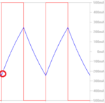
You want an initial condition I(t=0) that belongs to the periodical steady state solution, in other words the decaying transient solution should have zero magnitude. The waveform in post #7 shows what it is.

ic.png

The solution can be very easily calculated for R=0 (triangular current waveform) and almost easy for R>0 (exponential current waveform) , as assumed in post #7.
 
  • Like
Reactions: CataM

    CataM

    Points: 2
    Helpful Answer Positive Rating
You want an initial condition I(t=0) that belongs to the periodical steady state solution, in other words the decaying transient solution should have zero magnitude. The waveform in post #7 shows what it is.
So you are backing up my theory shown in post #11. We want the particular case when R=0 to behave in the steady state like a more general case RL would behave. (I have explained that regarding the sinusoidal steady state)

The RL general case in the steady state has 0 DC current, which means we must set the initial condition (i(0)) for the particular case when R=0 in such a way that leads to 0 DC current.

For the case when R=0 (pure L), i(D*T)=Δi + i(0)=V/L *D*T +i(0) which is also equal to Idc+Δi/2 (because is a triangular wave). Now, Idc=0, then i(0)=Δi/2-Δi= -Δi/2 = Initial condition we must set.

That is what I was looking for, the reason behind how is the initial condition (i(0)) set.

Since you are backing me up, I will take this as a founded reason :-D in order to select the initial condition.

-------

For the sinusoidal steady state.
Since i(t)=-V/ωL *cos(ωt) + IC+V/ωL = -V/ωL *cos(ωt) + DC value
To back up the above reasoning, we want it to behave the same in the steady state as a RL would, which means, we must set DC value=0, which leads to set IC+V/ωL=0, which leads to IC=i(0)=-V/ωL

i(0)=-V/ωL is the nontrivial, unfounded explanation Physics books give when they plot the current waveform of a pure L circuit when excited with a sinusoidal voltage source. i(t)=-V/ωL *cos(ωt)=V/ωL *sin(ωt-Π/2) which is what we all know from the phasorial analysis.
 
Last edited:

I repeat: the boundary conditions must be provided and cannot be calculated the way you have done. There are different solutions of the same equation with different boundary conditions.

The question is: what is the current value at t=0? That is YOUR choice and you can select any value. The original equation will still be satisfied. You can add any DC value and that will still be a good solution. It simply does not matter.

YOU have to provide the integration constant (and YOU cannot calculate the same from the SAME equation).

I do not understand what is so difficult here: but there is a pole at the origin. Be careful.
 

I repeat: the boundary conditions must be provided and cannot be calculated the way you have done. There are different solutions of the same equation with different boundary conditions.

Don't agree. It's a rather simple approach. He wants to start with a current value that complies with the periodical steady state solution, there shouldn't be a decaying transient solution as seen in post #7. For a given driving voltage waveform, there's exactly one initial current value that achieves this. The value is correctly calculated for square wave and sine voltage waveform.

Nevertheless I agree that it isn't a big thing. But it's an every day's problem when you e.g. set up time domain simulations with a slowly decaying transient solution. You want to provide initial conditions that avoid huge pre run times before the steady state solution is reached.

- - - Updated - - -

Unfortunately I forgot one point. For the ideal case of a purely inductive load, the initial transient solution lasts forever, so any initial condition is possible. In a real circuit, the transient solution decays in a few seconds.
 
  • Like
Reactions: CataM

    CataM

    Points: 2
    Helpful Answer Positive Rating
Unfortunately I forgot one point. For the ideal case of a purely inductive load, the initial transient solution lasts forever, so any initial condition is possible. In a real circuit, the transient solution decays in a few seconds.
That was my problem. I was always starting with i(0)=0 and hence never arrived to the real steady state solution. I was in a loop of false steady state in which the DC current is different than zero, because the transient when R=0 is infinite.

If one starts with the wrong initial condition, it will have a false steady state because of infinite transient.
 

Don't agree. It's a rather simple approach..

The equation di/dt=sin(t) has infinite solutions that differ only in the integration constant.

And the integration constant cannot be calculated from the same equation - it must be provided.

For example i=-cost(t)+10 and i=-cos(t)+100 both satisfy the given equation and both are valid solutions.

You select the solution that fits your condition. (I knew only two kinds of boundary conditions but I checked https://mathworld.wolfram.com/BoundaryConditions.html - and discovered that they say there are three different types).

He wants to start with a current value that complies with the periodical steady state solution, there shouldn't be a decaying transient solution as seen in post #7.

That is not at all difficult, but the question will remain- is it physically meaningful?

The graph in post #7 is a superposition of periodic and a decay function. Theoretically speaking, the decay functions take infinite time to decay. But it is easy to extract the periodic part of the solution. But does it have any physical significance? (say the theory of damping)

Mathematically speaking, all the different integration constants are valid but you choose one over another for some reason. I am unable to follow the reason in the choice.
 

Theoretically speaking, the decay functions take infinite time to decay.
In any real circuit, it will decay in finite time (not considering superconducting inductors). This gives a clear motivation for the chosen initial condition.
 

Status
Not open for further replies.

Part and Inventory Search

Welcome to EDABoard.com

Sponsor

Back
Top