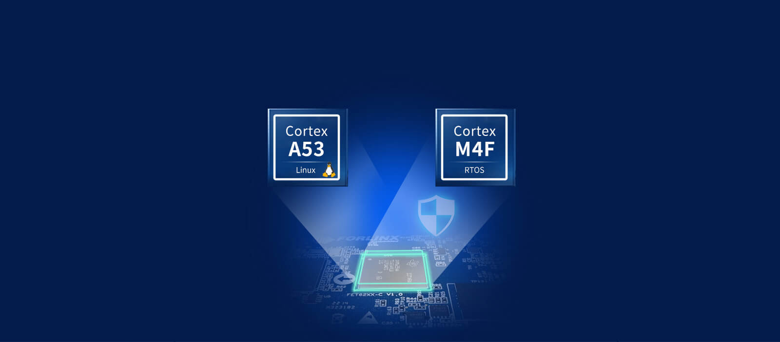
FORLINX embedded FET6254-C SOM is based on TI Sitara™ AM6254 industrial-grade processor, which is a multi-core heterogeneous processor with 4*Cortex-A53+Cortex-M4F architecture combination, in which the M4F core can be used to run Real-time operating system, access to peripherals, increase the functional safety of the system, and can also be used as a general-purpose MCU.

The following is a detailed introduction to the startup configuration, program writing and real-time simulation of the AM6254 processor M core program.
(2)The A core has two ways to start the M core program. One is to load /lib/firmware/am62-mcu-m4f0_0-fw during the startup process of core A kernel; the other is to execute /lib/firmware/m4fss_firmware/*. out file.
(3)Both am62-mcu-m4f0_0-fw and *.out files are executable files generated by compiling the M core program with CCS. am62-mcu-m4f0_0-fw is a binary executable file with small content. The *.out file contains address information, content Slightly larger.
(4)A core can detect whether the M core program is running according to the cat state command, so as to control the start and stop of the M core program. It is recommended to use the am62-mcu-m4f0_0-fw method, the program is automatically loaded and the configuration is simple.
SysConfig is a unified software configuration tool that uses a graphical configuration interface that can be used to configure clocks, peripherals, pins, and other components. It simplifies the configuration process of peripherals, and can find the conflicts of peripheral resources of complex products, which reduces the difficulty of development and improves the speed of software development. The function is similar to ST's STM32CubeMX.
The M-core development of AM6254 mainly uses CCS+SysConfig to complete the configuration, compilation and simulation of the program. SysConfig is generally embedded in the CCS software.
01. CCS
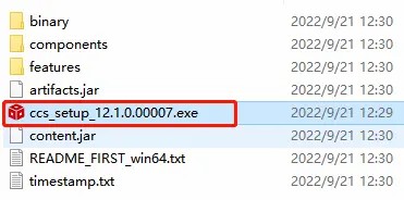
(1)Copy the CCS and SysConfig under the tools file of the M-core SDK package to another path. The path does not contain Chinese characters, otherwise the installation will report an error. Double-click the CCS installer to install it.
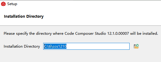
(2)Select the installation directory, it is recommended to select the root directory of each disk, such asC:\ti\ccs1210.
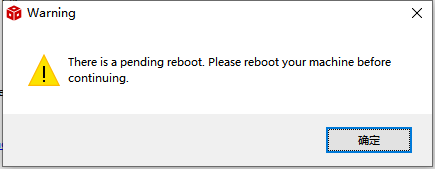
(3)Click next, and when the following warning appears, click OK.
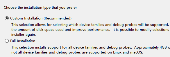
(4)The installation type is recommended to select "Custom Installation".
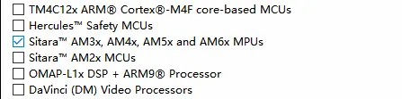
(5)Select the "Sitara AM3x, AM4x, AM5x and AM6x MPUs" option for the processor model.
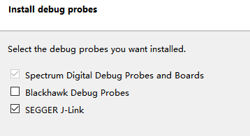
(6)The emulator selects SEGGER J-Link as follows
(7)Click next all the time to complete the installation.
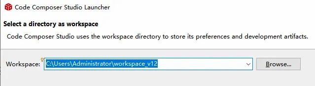
(8)Click the CCS icon on the desktop, select the workspace directory, and the subsequent projects loaded from the SDK will be saved in this workspace. If there is anti-virus software, please choose to allow all operations of the software or exit the anti-virus software.
02. SysConfig
(1) Double-click the SysConfig setup.exe installation program in the directory of the previous step to install it.
(2) Click next all the way to complete the installation.
03. Development environment confirmation
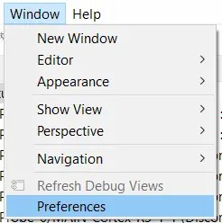
(1)Open the CCS software, select in the menu bar "Window > Preferences".
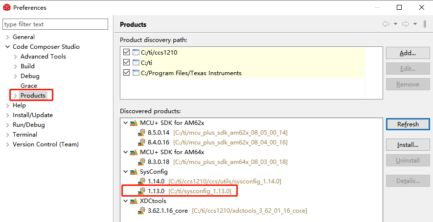
(2)Select "Code Composer Studio > Products" in the pop-up window to check whether SysConfig 1.13.0 is installed correctly.
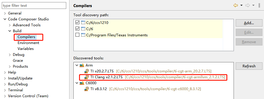
(3)Select "Code Composer Studio > Build > Compilers" to check whether TI CLANG 2.1.2.LTS is installed.
04. Simulation configuration
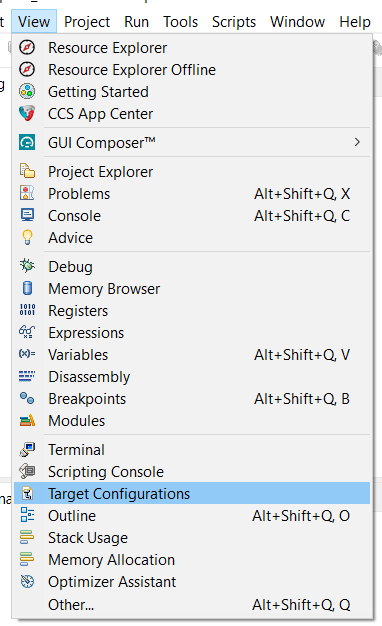
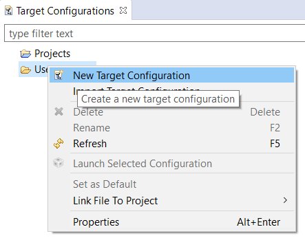
(1)menu bar selection "View > Target Configuration".
(2)Right-click on the User Defined folder and select "New Target Configuration" to create a new emulation configuration for the AM6254 processor.
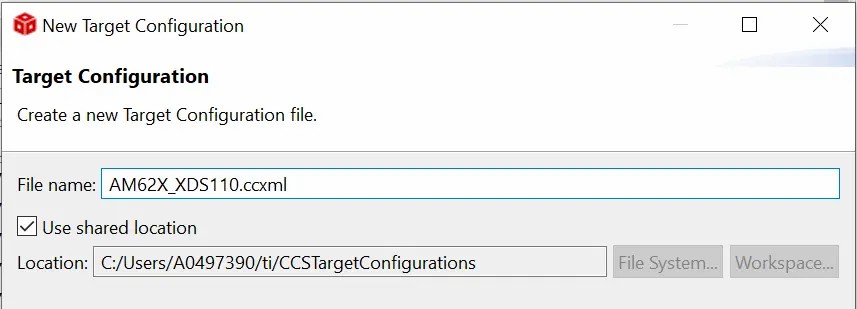
(3)Enter the simulation name in the new window, such as:AM6254_XDS110.ccxml.
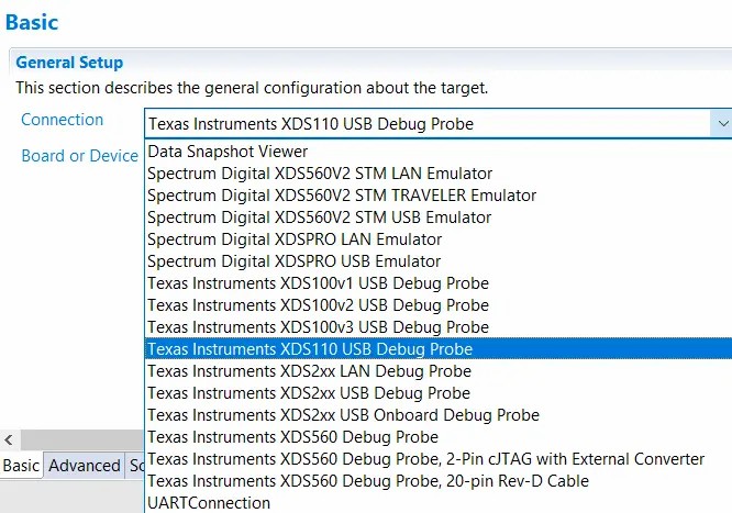
(4)Connectction emulator selects XDS110 USB Debug Probe
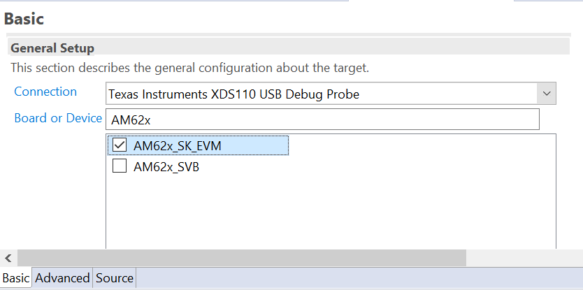
(5)Enter AM6254 in the Board or Device column and select "AM6254_SK_EVM". Click "Save" to save the configuration.
05. load, compile program
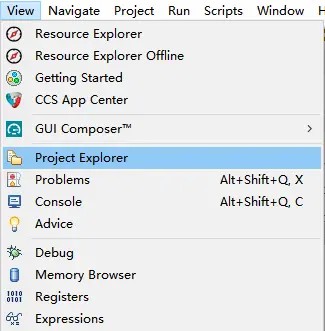
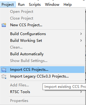
(1)Select "View > Project Explorer" from the menu bar, right-click on the menu bar and select "Project>Import CCS Projects".
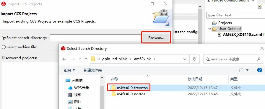
(2)In the pop-up window, select CCS Project. Click the "Browse" button to select the corresponding CCS project from the FreerM Core SDK package, such as loading the m4fss0-0_freertos routine from the \examples\drivers\gpio\gpio_led_blink directory. Click the "Finish" button.
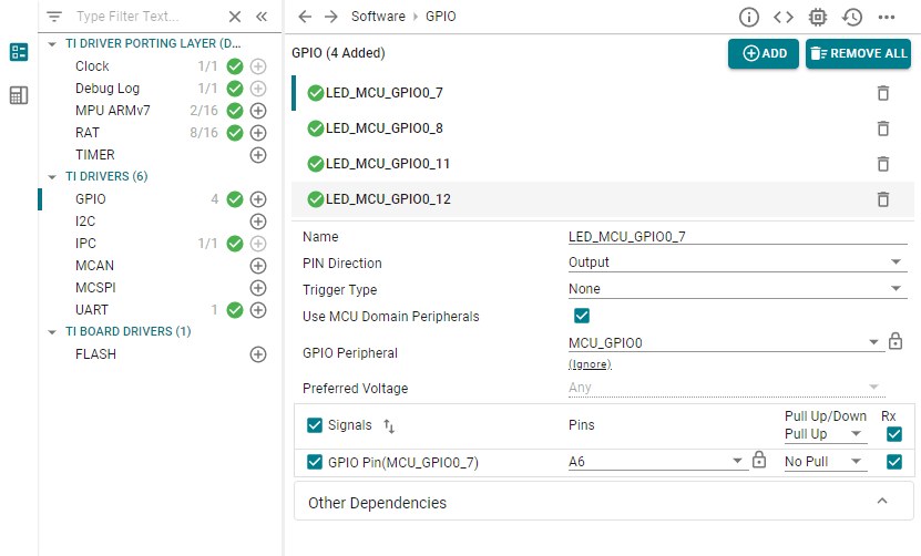
(3)Double-click "example.syscfg" in the project folder on the left, and you can see the corresponding graphical configuration of the kernel and peripherals. CCS will generate initialization code according to the SysConfig configuration and put it in the Generated Source folder. The function of SysConfig is very powerful, and users can experience it by themselves.
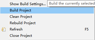
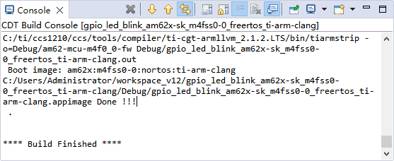
(4)Right-click the project folder on the left and select "Build Project", you can see the program compilation process, and finally display "Build Finished" to indicate that the compilation is complete.
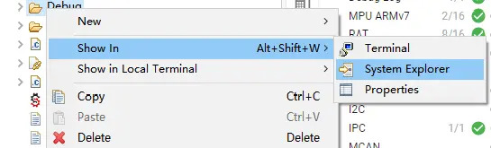
Right-click the Debug folder in the project directory on the left and select "Show In > System Explorer", and you can see the compiled am62-mcu-m4f0_0-fw and *.out files in the Debug directory.
02. Download file
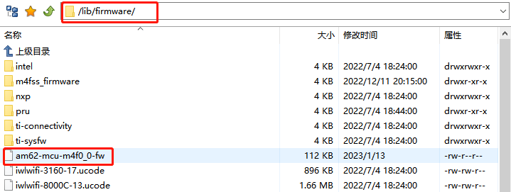
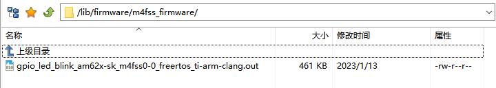
Use serial port Xmodem, network FTP, SCP, U disk, TF card, etc., put am62-mcu-m4f0_0-fw in /lib/firmware directory, and also put *.out in /lib/firmware/m4fss_firmware Under contents. Load am62-mcu-m4f0_0-fw during core A startup and run. If there is no am62-mcu-m4f0_0-fw file, you can also use the remoteproc framework to manually load the *.out file to start the M core program after the A core is started.
03. am62-mcu-m4f0_0-fw
Take gpio_led_blink as an example, put am62-mcu-m4f0_0-fw on the development board, restart the development board, power on and automatically run the M-core program, and the four green running lights will turn on and off in turn.
04. Remoteproc Frame
Take gpio_led_blink as an example, delete am62-mcu-m4f0_0-fw from the development board, restart the development board, the M core program will not be executed, enter the following commands in sequence, the M core program can be loaded, and the four green running lights will turn on and off.
1 cd /sys/class/remoteproc/remoteproc0 //1 Switch to the M-nuclear control directory
2 echo m4fss_firmware/gpio_led_blink_AM6254-sk_m4fss0-0_freertos_ti-arm clang.out > firmware //2 select program
3 echo start > state //3 choose to execute
4 cat state //4 View the running status of the M core program
5 echo stop > state //5 stop M core program
01. JTAG simulation
(1) To purchase a TI XDS-110 emulator, the firmware is required to support the AM6254 series.
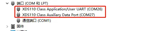
(2) Connect the computer and XDS-110 via USB. The computer will automatically install the XDS-110 driver, and you can see two XDS-110 serial ports under Device Management > Ports.
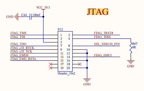
(3) The user can connect the computer to the development board through the XDS-110 and 20pin adapter board. Note that the XDS-110 pin 1 should correspond to the Jtag 1 pin of the development board.
02. UART OUTPUT
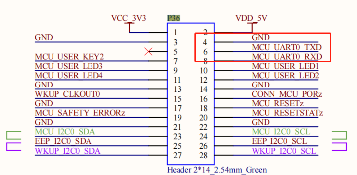
(1)Through USB to TTL, the computer can be connected to the M-core terminal of the development board (green P36), and the user can see the output information of the M-core program on the serial port. Note that the computer TXD is connected to the development board RXD, and the computer RXD is connected to the development board TXD. You can see the serial port number in the device manager.
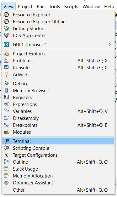
(2)In the menu bar in CCS, open "View > Terminal"
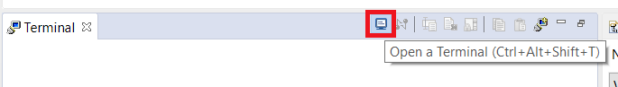
(3)Click the blue computer icon in the new window to create a new serial terminal.
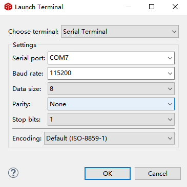
(4)In the uart configuration interface, select the serial port number, the baud rate is 115200, the data bit is 8 bits, no flow control, and the stop bit is 1 bit. In this way, the serial port output information can be seen on the CCS interface. Users can also set it in other serial port debugging software as above, and the effect is the same.
03. Hardware simulation
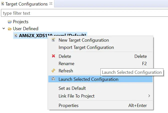
(1)Right-click AM6254_XDS110.ccxml in the Target Configuration column and select "Create Target Configuration", and CCS connects to AM6254 through JTAG.
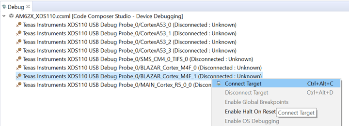
(2)If the Jtag connection is normal, you can see all the core information of AM6254 in the Debug column, right click on the M4F_1 core and select "Connect Target".
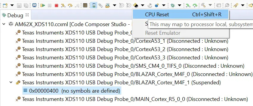
(3)Select from the menu bar drop-down options "CPU Reset".
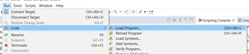
(4)To load the program, select from the menu bar "Run>Load>Load Program".
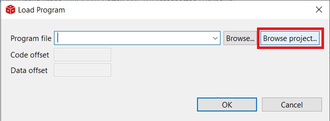
(5)Click the "Browse project" button to select the *.out file to be simulated.
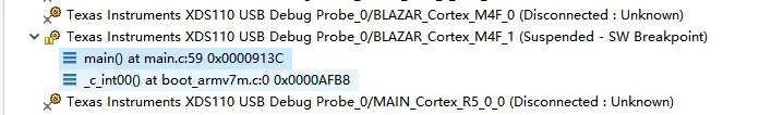
(6)In the Debug column, you can see that the M4F_1 core has jumped to the main function entry.
(7)Users can double-click the left mouse button in the code to set and cancel breakpoints, press F5 or F6 for single-step execution, and press F8 for full-speed execution. More functions and shortcut keys can be viewed under Run in the menu bar.
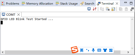
(8)You can see the output information of the M core on the CCS serial port bar or other serial port debugging tools.
04. Program Test
We take gpio_led_blink as an example to demonstrate the hardware emulation function.
The following is a detailed introduction to the startup configuration, program writing and real-time simulation of the AM6254 processor M core program.
M core program starts
(1)The A-core and M-core of AM6254 are independent from each other in design. Theoretically, the operating state of A-core has no influence on the operation of M-core, and its stability is greatly improved. However, most of the official information currently released must be loaded with the M core program by the A core, and this part of the official will continue to be upgraded in the future.(2)The A core has two ways to start the M core program. One is to load /lib/firmware/am62-mcu-m4f0_0-fw during the startup process of core A kernel; the other is to execute /lib/firmware/m4fss_firmware/*. out file.
(3)Both am62-mcu-m4f0_0-fw and *.out files are executable files generated by compiling the M core program with CCS. am62-mcu-m4f0_0-fw is a binary executable file with small content. The *.out file contains address information, content Slightly larger.
(4)A core can detect whether the M core program is running according to the cat state command, so as to control the start and stop of the M core program. It is recommended to use the am62-mcu-m4f0_0-fw method, the program is automatically loaded and the configuration is simple.
Build a development environment and program compilation
CCS (Code Composer Studio) is an integrated development environment (IDE) developed by TI for microcontrollers and processors, which includes a complete set of tools for developing and debugging embedded applications. Such as C/C++ compiler, source code editor, project build environment, debugger, performance analyzer and many other functions. Similar to Keil or IAR, users can use CCS to compile and simulate programs.SysConfig is a unified software configuration tool that uses a graphical configuration interface that can be used to configure clocks, peripherals, pins, and other components. It simplifies the configuration process of peripherals, and can find the conflicts of peripheral resources of complex products, which reduces the difficulty of development and improves the speed of software development. The function is similar to ST's STM32CubeMX.
The M-core development of AM6254 mainly uses CCS+SysConfig to complete the configuration, compilation and simulation of the program. SysConfig is generally embedded in the CCS software.
01. CCS
(1)Copy the CCS and SysConfig under the tools file of the M-core SDK package to another path. The path does not contain Chinese characters, otherwise the installation will report an error. Double-click the CCS installer to install it.
(2)Select the installation directory, it is recommended to select the root directory of each disk, such asC:\ti\ccs1210.
(3)Click next, and when the following warning appears, click OK.
(4)The installation type is recommended to select "Custom Installation".
(5)Select the "Sitara AM3x, AM4x, AM5x and AM6x MPUs" option for the processor model.
(6)The emulator selects SEGGER J-Link as follows
(7)Click next all the time to complete the installation.
(8)Click the CCS icon on the desktop, select the workspace directory, and the subsequent projects loaded from the SDK will be saved in this workspace. If there is anti-virus software, please choose to allow all operations of the software or exit the anti-virus software.
02. SysConfig
(1) Double-click the SysConfig setup.exe installation program in the directory of the previous step to install it.
(2) Click next all the way to complete the installation.
03. Development environment confirmation
(1)Open the CCS software, select in the menu bar "Window > Preferences".
(2)Select "Code Composer Studio > Products" in the pop-up window to check whether SysConfig 1.13.0 is installed correctly.
(3)Select "Code Composer Studio > Build > Compilers" to check whether TI CLANG 2.1.2.LTS is installed.
04. Simulation configuration
(1)menu bar selection "View > Target Configuration".
(2)Right-click on the User Defined folder and select "New Target Configuration" to create a new emulation configuration for the AM6254 processor.
(3)Enter the simulation name in the new window, such as:AM6254_XDS110.ccxml.
(4)Connectction emulator selects XDS110 USB Debug Probe
(5)Enter AM6254 in the Board or Device column and select "AM6254_SK_EVM". Click "Save" to save the configuration.
05. load, compile program
(1)Select "View > Project Explorer" from the menu bar, right-click on the menu bar and select "Project>Import CCS Projects".
(2)In the pop-up window, select CCS Project. Click the "Browse" button to select the corresponding CCS project from the FreerM Core SDK package, such as loading the m4fss0-0_freertos routine from the \examples\drivers\gpio\gpio_led_blink directory. Click the "Finish" button.
(3)Double-click "example.syscfg" in the project folder on the left, and you can see the corresponding graphical configuration of the kernel and peripherals. CCS will generate initialization code according to the SysConfig configuration and put it in the Generated Source folder. The function of SysConfig is very powerful, and users can experience it by themselves.
(4)Right-click the project folder on the left and select "Build Project", you can see the program compilation process, and finally display "Build Finished" to indicate that the compilation is complete.
Download program
01. Target fileRight-click the Debug folder in the project directory on the left and select "Show In > System Explorer", and you can see the compiled am62-mcu-m4f0_0-fw and *.out files in the Debug directory.
02. Download file
Use serial port Xmodem, network FTP, SCP, U disk, TF card, etc., put am62-mcu-m4f0_0-fw in /lib/firmware directory, and also put *.out in /lib/firmware/m4fss_firmware Under contents. Load am62-mcu-m4f0_0-fw during core A startup and run. If there is no am62-mcu-m4f0_0-fw file, you can also use the remoteproc framework to manually load the *.out file to start the M core program after the A core is started.
03. am62-mcu-m4f0_0-fw
Take gpio_led_blink as an example, put am62-mcu-m4f0_0-fw on the development board, restart the development board, power on and automatically run the M-core program, and the four green running lights will turn on and off in turn.
04. Remoteproc Frame
Take gpio_led_blink as an example, delete am62-mcu-m4f0_0-fw from the development board, restart the development board, the M core program will not be executed, enter the following commands in sequence, the M core program can be loaded, and the four green running lights will turn on and off.
1 cd /sys/class/remoteproc/remoteproc0 //1 Switch to the M-nuclear control directory
2 echo m4fss_firmware/gpio_led_blink_AM6254-sk_m4fss0-0_freertos_ti-arm clang.out > firmware //2 select program
3 echo start > state //3 choose to execute
4 cat state //4 View the running status of the M core program
5 echo stop > state //5 stop M core program
M core program simulation
The FORLINX embedded FET6254-C SOM supports JTAG's hardware simulation function for the M core. Users can set breakpoints through JTAG in CCS, view and modify variables in real time, run programs at full speed or step by step, and improve program troubleshooting. In addition, AM6254 also supports serial port output debugging.01. JTAG simulation
(1) To purchase a TI XDS-110 emulator, the firmware is required to support the AM6254 series.
(2) Connect the computer and XDS-110 via USB. The computer will automatically install the XDS-110 driver, and you can see two XDS-110 serial ports under Device Management > Ports.
(3) The user can connect the computer to the development board through the XDS-110 and 20pin adapter board. Note that the XDS-110 pin 1 should correspond to the Jtag 1 pin of the development board.
02. UART OUTPUT
(1)Through USB to TTL, the computer can be connected to the M-core terminal of the development board (green P36), and the user can see the output information of the M-core program on the serial port. Note that the computer TXD is connected to the development board RXD, and the computer RXD is connected to the development board TXD. You can see the serial port number in the device manager.
(2)In the menu bar in CCS, open "View > Terminal"
(3)Click the blue computer icon in the new window to create a new serial terminal.
(4)In the uart configuration interface, select the serial port number, the baud rate is 115200, the data bit is 8 bits, no flow control, and the stop bit is 1 bit. In this way, the serial port output information can be seen on the CCS interface. Users can also set it in other serial port debugging software as above, and the effect is the same.
03. Hardware simulation
(1)Right-click AM6254_XDS110.ccxml in the Target Configuration column and select "Create Target Configuration", and CCS connects to AM6254 through JTAG.
(2)If the Jtag connection is normal, you can see all the core information of AM6254 in the Debug column, right click on the M4F_1 core and select "Connect Target".
(3)Select from the menu bar drop-down options "CPU Reset".
(4)To load the program, select from the menu bar "Run>Load>Load Program".
(5)Click the "Browse project" button to select the *.out file to be simulated.
(6)In the Debug column, you can see that the M4F_1 core has jumped to the main function entry.
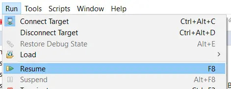
(7)Users can double-click the left mouse button in the code to set and cancel breakpoints, press F5 or F6 for single-step execution, and press F8 for full-speed execution. More functions and shortcut keys can be viewed under Run in the menu bar.
(8)You can see the output information of the M core on the CCS serial port bar or other serial port debugging tools.
04. Program Test
We take gpio_led_blink as an example to demonstrate the hardware emulation function.
- (1) Put the am62-mcu-m4f0_0-fw on the development board, this step must be there, otherwise it cannot be simulated.
- (2) Restart the development board, operate according to step 3 hardware simulation link, and enter the main function.
- (3) Execute the program step by step by pressing the F6 button, you can see the four green running lights on and off, and you can also see the program output information from the M core serial port.