shredder929
Junior Member level 3
- Joined
- Jul 1, 2019
- Messages
- 27
- Helped
- 1
- Reputation
- 2
- Reaction score
- 2
- Trophy points
- 3
- Location
- Massachusetts
- Activity points
- 408
I'm trying to make a peak detector for small voltages (<500mV). Normally a capacitor would hold the peak, and a diode prevents charge from flowing back when the voltage swings lower than the held peak. I can't use a diode to control current to the capacitor because it's such a small voltage, the lowest expected peak being 40mV.
So I'm playing around with different ways of preventing the charge from flowing back to the op-amp that sources the signal. What I thought I'd do is use a JFET instead. When the gate is 0V, the source follows the drain with only ~5mV difference. When I pull Vgs low, it gets pinched off.
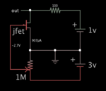
It's generally working as expected but there's some weirdness that goes on. It's present in the ideal model and gets worse when I use models of real parts. I've attached screenshots of the simple setup I'm simulating, a graph of the output with an ideal JFET, and with a real JFET (the 2N3819). What is going on with those dips? Why isn't it holding it straight like I'd expect? I've been trying to find a pattern but it doesn't seem to occur with any rhyme or reason.
Any help is appreciated, thank you!
https://imgur.com/a/Qs90TjS
