Welcome to our site! EDAboard.com is an international Electronics Discussion Forum focused on EDA software, circuits, schematics, books, theory, papers, asic, pld, 8051, DSP, Network, RF, Analog Design, PCB, Service Manuals... and a whole lot more! To participate you need to register. Registration is free. Click here to register now.
Hi i need help in designing folded monopole working at 1ghz in HFSS.
i need help in modeling the structure of the antenna.
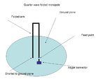
How can i connect folded arm to the ground plane/sheet in hfss as shown in attached file.
It would make it easier if you posted an image, which someone can see without loading proprietry 3rd party products. More people will look at your design if they can see it inline, and not have to load up other software.
To look at your design, I suspect the real problem you have is nothing to do with drawing the metalic objects, which is trivual, but to entering the capacitors.
HFSS is a 3D EM solver, so ideally you want to draw the capacitor plates, and dielectric. That's the most accurate way to do it. But you can draw a sheet object, and apply an RLC boundary to that sheet object. You then just enter the value of the component. I've no idea how much accuracy will suffer doing this though. I would be tempted to make the size of the sheet the same size as your capacitor. Of course, your capacitor will be a 3D object, but I'd be tempted to ignore the thinnest dimesion, and consider the sheet to be the size of the two largest dimensions.
I would add, I have never used the RLC boundary, don't know how accurate your simulations will be, and don't know if I'm right in sizing the sheet the way I suggested.
I would epect that as the capacitor gets physically larger compared to the rest of the antenna, the accuracy will deteriorate.
This is different to what you originally showed, as previously you had capacitors.
From the top of my memory you are going to need to
Draw the groundplane - do you want to assume it is infinite in extent?
Draw the 3 arms of the folded monopole - probably cylinders are boxes.
Define a solution type
Unite various objects
Draw a sheet for the N connector (unless you want to model the actual connector too).
Create an airbox
Add a radiation boundary
Set a solution frequency
Add a frequency sweep if you want it
Add a waveport - assuming the antenna is fed from below. If not a lumped port is probably best
All the things I forgot
What part are you stuck on? If you stuck or more than a couple of these, then I suggest you work your way through the tutorials first. But if not, and you list what your problems are, someone will probably be able to help you.
It would help if you attached your .hfss file as a zipfile.
This site uses cookies to help personalise content, tailor your experience and to keep you logged in if you register.
By continuing to use this site, you are consenting to our use of cookies.