tefavolc
Newbie level 5
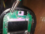
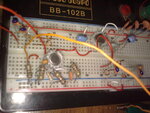
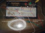
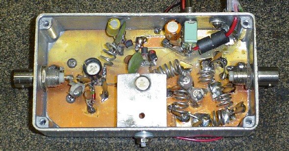
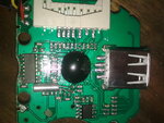
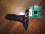
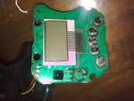
i am working on fm power amplifer , i ve designed the circuit on the orcad , and implement it on the breadboard . i bough a car fm transmitter to use it as rf source .the fm modulator contain kt0803l ic which by looking at its datasheet has rf o/p at the pin no 16 . i connect pin 16 to the amplifer i/p and the ground of the transmitter to the ground of the amplifer . but the problem is that the radio is receiving the fm signal from the transmitter and i didnt see any type of antenna in it in order to remove it .
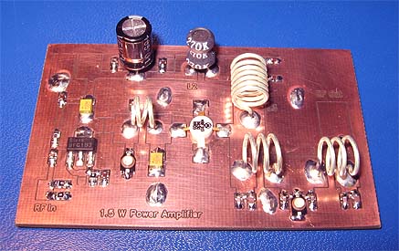
i ve upload the pic of the transmitter and the amplifer hoping any one would help me to make the fm stop transmitting and direct the o/p rf to the amplifer .
i ve upload the pic of the transmitter and the amplifer hoping any one would help me to make the fm stop transmitting and direct the o/p rf to the amplifer .
")