Continue to Site

Welcome to EDAboard.com

Welcome to our site! EDAboard.com is an international Electronics Discussion Forum focused on EDA software, circuits, schematics, books, theory, papers, asic, pld, 8051, DSP, Network, RF, Analog Design, PCB, Service Manuals... and a whole lot more! To participate you need to register. Registration is free. Click here to register now.

Flyback vs Forward : guide me to choose.

Status
Not open for further replies.

pawan kumar

Member level 4
Joined
Jan 31, 2012
Messages
73
Helped
5
Reputation
10
Reaction score
5
Trophy points
1,298
Location
Chennai
Activity points
1,894
Hello Friends,

I want to design a power supply with the following configuration:

+24V Input with 3 outputs :

+17V, 400mA
-17V, 230mA
+5V, 3A.

All are isolated by 2kV.
Feedback : OPTO
I have gone through application notes of flyback controllers similar to this config. +5V is fully regulated and the other two are quasi regulated.

I want guidance on selecting the topology : Is this possible with Forward too? if yes, which one would be better?

Please suggest. I am new to Analog.
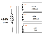
multi_secondary.png
 

Your design has three secondary windings...

So your primary must carry exactly the right waveform to provide for all three outputs? This will be a major achievement. I think you'll need to wind and remove lots of turns of wire, before you find the correct combination.

Furthermore will your loads be unchanging? Then it might work. However if one load draws more current, then the other two will drop in voltage. And if one supply draws less current, the other two will rise in voltage. I believe you'll need to put resistive regulation on all three supplies. This wastes power.

The beauty of switched-coil regulation is that you adjust frequency and duty cycle so that you only draw as much power (from your 24V supply) as you need. You do not generate excess heat.

I recommend that you use a flyback/ forward converter to obtain 5V at 3A. That is where a step-down transformer will benefit you most.

Construct a buck converter to get +17V.

And a buckboost to get -17V. Or a negative charge pump.
 
Forward topology is not suitable for multi output supplies, unless you intend to have post regulation on the auxiliary outputs. Flyback is better, but expect %5-10 of error on the aux outputs.

For your power level, flyback is perfectly adequate, no reason to go with a higher power topology.
 
Thank You Friends @BartheRad and Mtwieg for your time.

I intend to have a post Regulation through LDO for both 17V outputs.

And, for -17V, I thought reversing the terminals would be fine. Would'nt it.
 

And, for -17V, I thought reversing the terminals would be fine. Would'nt it.

Yes, but it will be AC coming from the secondary. When you put a diode on it, you'll get DC.

Do you want a common ground between +17 and -17? You may need to test a few combinations of terminals and diode orientations, to find the configuration that gives you optimal results with the flyback waveforms.
 
Status
Not open for further replies.

Similar threads

Part and Inventory Search

Welcome to EDABoard.com

Sponsor

Back
Top