strape81
Junior Member level 3
Hi all,
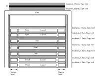
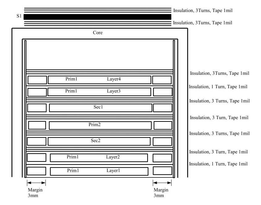
I am currently designing a flyback converter with sandwich winding and I want to reduce the parasitic capacitances between the windings.
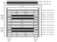
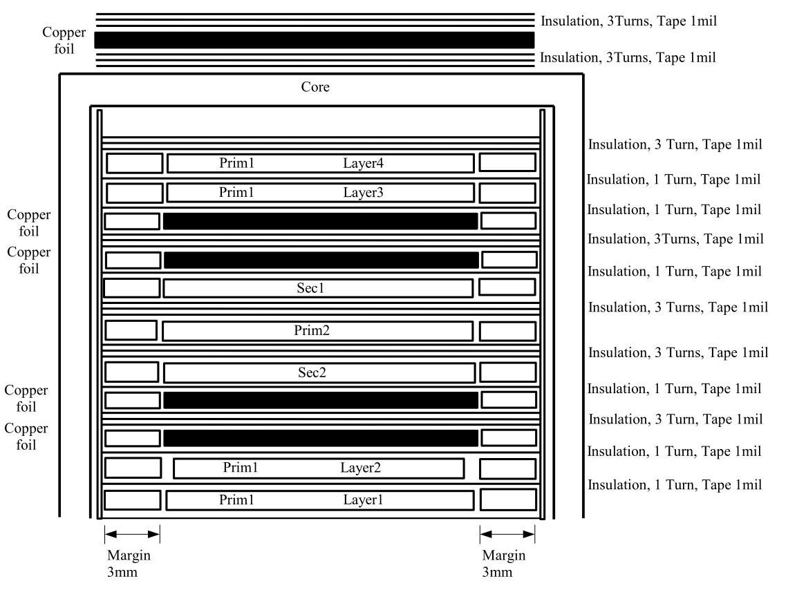
In picture 1 you can see the design without copper foil shielding and in picture 2 you can see where I have put them.
Taking into consideration these two configurations I have the following problem:
with the copper foils between the windings I cannot get the proper primary winding inductance (440uH instead of 930uH). Without the foils the right value is there.
How does the copper foil affect the inductance at the primary winding???
What do I do or understand wrong???
I measure the inductance using a LCR bridge.
Thanks a lot in advance for helping me with this problem!!!
I am currently designing a flyback converter with sandwich winding and I want to reduce the parasitic capacitances between the windings.
In picture 1 you can see the design without copper foil shielding and in picture 2 you can see where I have put them.
Taking into consideration these two configurations I have the following problem:
with the copper foils between the windings I cannot get the proper primary winding inductance (440uH instead of 930uH). Without the foils the right value is there.
How does the copper foil affect the inductance at the primary winding???
What do I do or understand wrong???
I measure the inductance using a LCR bridge.
Thanks a lot in advance for helping me with this problem!!!