Continue to Site

Welcome to EDAboard.com

Welcome to our site! EDAboard.com is an international Electronics Discussion Forum focused on EDA software, circuits, schematics, books, theory, papers, asic, pld, 8051, DSP, Network, RF, Analog Design, PCB, Service Manuals... and a whole lot more! To participate you need to register. Registration is free. Click here to register now.

Flyback SMPS with Myrra 74015 transformer

Status
Not open for further replies.

Embedded_Geek

Full Member level 6
Joined
Jul 5, 2010
Messages
340
Helped
58
Reputation
116
Reaction score
56
Trophy points
1,318
Location
Germany
Activity points
2,948
Hello Members,

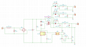
I made a Flyback SMPS with Myrra 74015 transformer and TNY276 control chip. Unfortunately I see that when input voltage is 230VAC the output it not the expected voltage. But when I reduce the input AC volatage to approx. 120VAC then I get the correct expected output voltage.
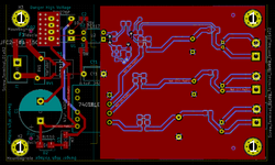
Could you please point to the possible reasons for this behaviour. I have attached the screenshot of the schematics.

Many thanks,
Embedded_Geek
 

Attachments

  • smps.png
    smps.png
    121.2 KB · Views: 253

Hi,

Please give clear values:
* what voltage do you expect
* what voltage do you measure? At wich load current?

Klaus
Thanks for the reply.
Please find the details below:
* This SMPS consist of 3 outputs (5V, 12V and 24V). Therefore, I expect these voltages at the output
* At 5V side as soon as I power ON I see around 3V then slowly it ramps down to 1V. When I disconnect the AC power (230VAC) as soon as the voltage across DC capacitor at the primary side goes below 120VDC I see that all the outputs are expected value (5V, 12V and 24V).
All the above observations were done at zero load current.

Thanks in advance,
Embedded_Geek
 

Hi,

Why/how did you choose the transformer to this application. (Not saying it's right or wrong)
I just see that the switcher model is not listed in the transformer's datasheet.

Did you follow PCB layout considerations very closely? In doubt show your PCB layout.

Klaus
 
Hi,

I doubt this is your problem at all from what you describe.

What happens if you make R3 e.g. 330R?

I'm not sure if I'm getting something embarrassingly wrong here, I probably am knowing myself..., but if I (firstly, choose to ignore the parallel value of the feedback voltage divider itself [in parallel with any load resistor - that you don't have at present, you say] in parallel with the 1.034k into the TL431) calculate:
5V - (Vf LED + Vf TL431) e.g. 5V - (1.7V + 2.495V) = 5V - 4.195V = 0.805V
Then 0.805V/1.034kOhms = 778uA iK...

TL431 never works for me with less than at least >1mA iK.
--- Updated ---

...So, at the other extreme: (5V - (Vf LED + Vf TL431))/34 Ohms = ~23mA. That must return to ground through the TL431, then. Is that right? Does that mean that the TL431 either has <1mA or >23mA iK?
 
Last edited:
Hi,

Why/how did you choose the transformer to this application. (Not saying it's right or wrong)
I just see that the switcher model is not listed in the transformer's datasheet.

Did you follow PCB layout considerations very closely? In doubt show your PCB layout.

Klaus
The transformer's datasheet mentions TNY266. Atleast I do not see a major difference in parameters between TNY266 and TNY276 which could lead to such a behaviour.

Design considerations are done, in fact few years back I had designed PCB not keeping this design considerations but it worked.
--- Updated ---

Hi,

I doubt this is your problem at all from what you describe.

What happens if you make R3 e.g. 330R?

I'm not sure if I'm getting something embarrassingly wrong here, I probably am knowing myself..., but if I (firstly, choose to ignore the parallel value of the feedback voltage divider itself [in parallel with any load resistor - that you don't have at present, you say] in parallel with the 1.034k into the TL431) calculate:
5V - (Vf LED + Vf TL431) e.g. 5V - (1.7V + 2.495V) = 5V - 4.195V = 0.805V
Then 0.805V/1.034kOhms = 778uA iK...

TL431 never works for me with less than at least >1mA iK.
--- Updated ---

...So, at the other extreme: (5V - (Vf LED + Vf TL431))/34 Ohms = ~23mA. That must return to ground through the TL431, then. Is that right? Does that mean that the TL431 either has <1mA or >23mA iK?
Since R3 is 1K Ohms and parallel to the LED of PC817, then my understanding is that majority of the curent should pass through the internal led and not via R3. I am also little confused ;)
--- Updated ---

Hi,

Why/how did you choose the transformer to this application. (Not saying it's right or wrong)
I just see that the switcher model is not listed in the transformer's datasheet.

Did you follow PCB layout considerations very closely? In doubt show your PCB layout.

Klaus
--- Updated ---

@d123 I tried ba making R3 to 330ohms, but unfortunately the behaviour is still the same.
Thanks,
 

Attachments

  • smps_layout.png
    smps_layout.png
    258.4 KB · Views: 138
Last edited:

Hi,

Thanks. I'd 'unhelped me' with my useless answers, friend, I doubt they are genuinely helpful because I'm sure I'm talking absolute rubbish without understanding well how the opto and TL431 interact. :rolleyes: Thanks for trying the resistor idea all the same.
 
If you are actually using a 30V rated schottky diode for the 24V output, the observed behavior is most likely caused by diode reverse breakdown and respective overcurrent shutdown of the switcher. Please calculate the maximum reverse voltage of D6 with 230 V AC input, you get about 100 V.
 
Hi again,

I was having a quick browse of the datasheet for the TinySwitch-II Family out of curiosity, and couldn't help but notice the BP/M connection in your schematic is different to figure 14 on page 8, described as: "The circuit shown in Figure 14 is a low cost, high efficiency, flyback power supply designed for 12 V, 1 A output from universal input using the TNY278." but the 'typical application' on page 1 is not the same as yours either. I also read that EN/UV has a current range window of 75 to 115uA and then it shuts off, but your resistor is 3.9M and in the schematic there it's 3.6M, so that can't be the problem. Page 2, figure 2 - is it possible that the cap to ground or something about the EN connection makes the device stop switching? I'd guess it was either the En pin or the BP/M pin that causes the issue - guess being the operstive word.
 
If you are actually using a 30V rated schottky diode for the 24V output, the observed behavior is most likely caused by diode reverse breakdown and respective overcurrent shutdown of the switcher. Please calculate the maximum reverse voltage of D6 with 230 V AC input, you get about 100 V.
Thanks for the reply.
In the meantime, I disconnected the D6, D5 and their snubber circuit. Then I see that the voltage at 5V output is only 0.5V. Looks like its not at all switching.

Also how did you exactly calculate the reverse voltage to 100V?

Thanks in advance,
--- Updated ---

Hi again,

I was having a quick browse of the datasheet for the TinySwitch-II Family out of curiosity, and couldn't help but notice the BP/M connection in your schematic is different to figure 14 on page 8, described as: "The circuit shown in Figure 14 is a low cost, high efficiency, flyback power supply designed for 12 V, 1 A output from universal input using the TNY278." but the 'typical application' on page 1 is not the same as yours either. I also read that EN/UV has a current range window of 75 to 115uA and then it shuts off, but your resistor is 3.9M and in the schematic there it's 3.6M, so that can't be the problem. Page 2, figure 2 - is it possible that the cap to ground or something about the EN connection makes the device stop switching? I'd guess it was either the En pin or the BP/M pin that causes the issue - guess being the operstive word.
I measured the voltage at BP/M and it is 5.9V exactly as per the datasheet. So, probably this pin isn't the problem. EN/UV is also dependent on the feedback (but not sure yet, as to what's wrong is going on here) :(

Thanks,
 

Status
Not open for further replies.

Part and Inventory Search

Welcome to EDABoard.com

Sponsor

Back
Top