Continue to Site

Welcome to EDAboard.com

Welcome to our site! EDAboard.com is an international Electronics Discussion Forum focused on EDA software, circuits, schematics, books, theory, papers, asic, pld, 8051, DSP, Network, RF, Analog Design, PCB, Service Manuals... and a whole lot more! To participate you need to register. Registration is free. Click here to register now.

FLYBACK DESIGN, PSR, BCM Mode, Constant current output design, Calculations

Status
Not open for further replies.

aj_augus

Newbie level 6
Joined
Aug 25, 2020
Messages
12
Helped
0
Reputation
0
Reaction score
0
Trophy points
1
Activity points
96
Hi,

Can anyone help with materials for the designing of LED drivers (Home applications). Transformer design values such as Primary inductance....etc. I referred so many equations, each of them looks different and as there are different modes, DCM,CCM, and different ICs, I am totally confused with the calculations.

Please help
--- Updated ---

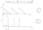
I have got a transformer design with equations for PSR, DCM transformer design. I don't know what are the parameters different from DCM from BCM design. As my IC is working with Critical Conduction Mode(It is also called BCM I guess).
 
Last edited:

A rule of thumb is to design a flyback for 50 percent duty cycle. Thus you have leeway to change the ratio between the first and last half of a cycle.

For switching frequency 10 to 30 kHz is easy to work with.

To experiment 100uH to 1 mH is a reasonable primary value for the transformer.

However close or distant the transformer arrives to your design specs, you can usually adjust frequency and duty cycle to produce desired output.

Simple demo, lacks snubber network. Lacks current regulation.

Simple clock-driven flyback 50 VDC to bri whi led 12V.png
 

Some information is missing from your post, namely total power, Vin, Vout, ( max I out ) any size or efficiency constraints ... initial choice of controller ... ?
 

Hi,

I just have confusion with the calculation of Primary inductor Values, I have equations used for DCM mode, But for CCM and BCM, some values should be different right?
If I contact some Transformer Suppliers, some basic information I have to give. including Lp.

* Also, The different kinds of Flybacks Easily can understand the basic functionality differences. But difficult to get simple calculations to follow.

Each IC manufacturer's datasheet gives different complicated equations.

PSR, SSR
CC, CV
DCM,CCM, BCM

* Load resistor will make an important role in the transformer design? Also for an IC I have, the datasheet shows the below details for frequency. So which frequency should be chosen as the switching frequency? TONmax?
1608707297876.png


Application is: LED DRIVER
This IC is in Critical Conduction Mode
--- Updated ---

Some information is missing from your post, namely total power, Vin, Vout, ( max I out ) any size or efficiency constraints ... initial choice of controller ... ?

Yeah, I have this information, but can I use the same equations used for DCM in BCM? That is the first doubt. Ex. 220VAC, 18W output, CC 0.5A, 18 to 36Vout
EFD15 core can be used.
 
Last edited:

You usually wind to get full layers,......and sometimes have to use parallel strands to get this.......full layers generally means less leakage L...but also its easy to wind the next layer on top of a full layer .

How to pick number of turns in transformer
Your question about the actual numbers of turns is a very common one.
Turn it round, and tell yourself, you can have as many , or as few turns as you like as long as…

1…..The number of turns for a coil generally fits across the bobbin length (even if you do multiple layers) …you generally get better coupling if you use the full bobbin width.
2…you can get your turns ratio……for example, if you want a turns ratio of 3.5, then you cant pick a single turn primary because you cant have a 3.5 turn secondary.
3….You don’t saturate the core
4….you don’t suffer too high core losses
5…the turns fit on the bobbin space
6…you can terminate a coil to the former pin (eg a 3mm thick wire wont be easily solderable to a small former pin)
7…you dont have too many layers, as if you do , you may get proximity effect problems.
8…you dont get too much winding loss
9….you get leakage inductance reduced to your requirement
10….the turns fit on the bobbin…turns being litz or double coil etc
……………..
So make out a spreadsheet and carry it through….when you see you violate some condition, just change it till it converges to the right solution.
If you don’t know what number of turns to start with…pick any number out of your head and try and work it through…if its not viable your spreadsheet calculations will soon flag this up to you and you will be able to see if you need to reduce or increase it.
--- Updated ---


Attached are some flyback simualtions in the free LTspice.

Remember that NS/NP = SQRT(LS/LP)

Also, if you are really stuck about what number of turns to do...then pick a number out of the air and try and make out the winding spec...you will soon see where it goes wrong and put it right
(you will need the ferroxcube or tdk ferrite core catalog so you can measure out the bobbins for the windings.)

Also, for a flyback, if you dont know what the primary inductance should be...then pick something silly like 100nH...and work it through...you will soon see whats wrong and correct it

...and run the sims to get youself into the nervous system of a flyback converter
 

Attachments

  • Flyback _CCM.zip
    1.6 KB · Views: 137
  • Flyback _DCM.zip
    1.7 KB · Views: 115
Last edited by a moderator:
Before going further, it is good for you to consult the attached Flyback primary and secondary current waveforms.
There is 1 and 2.
Which is good, and which is bad?
I believe you should know this before continuing

(i know i did not draw well...but pretend that Vin,Vout, and Pout are the same for each case.)
 

Attachments

  • Flyback SMPS _Pri and Sec currents.jpg
    Flyback SMPS _Pri and Sec currents.jpg
    52.2 KB · Views: 153

Neither above is very good - for an off line application the Duty Cycle will vary somewhat over a mains cycle - operation near 50% for most of the mains cycle is to be aimed at ...
 

Thanks, it was badly drawn and explained by me, ........Supposing your 240vac offline flyback output is 10V and 6A (doable with eg an innoswitch)...then 50% duty , and approx BCM operation, is going to give you a secondary current peak of 12A. This is very high, and i believe you would look to reduce this by increasing the secondary side duty cycle to get such a peak down...ie, increasing it to some 80%.....ie a primary duty of 20% max.
(considering a big pri cap and Vin of approx 300V min)
(obviously the NS/NP would be suitably adjusted to facilitate this and stay in approx bcm)
 

Actually the sec side peak current will be 4 x 6 = 24A for 50% pwm BCM or DCM operation ... ( 6 A ave x 2 if conducting for 50% of the time, x 2 to account for the fact the wave-shape is triangle not square )
 
  • Like
Reactions: zenerbjt

    Z

    Points: 2
    Helpful Answer Positive Rating
Thanks yes, my post of #9 as you say, is in error (peak current too low). In fact, you have further exampled my point to the original poster, that they should design to avoid these peaks currents like 24A
 

1609051534275.png


In the case in BCM Transformer, can anyone say which frequecncy should I choose? Fsw?
 

It's useless to post timing specifications without mentioning the referred converter IC and application circuit.

Also the intended operation isn't completely clear. I guess you are targetting to PFC with the said BCM mode. In this case, the switcher is operated with constant on time and respectively variable frequency. It would be helpful to sketch voltage and current waveforms varying over a mains half cycle.
 

1609067273863.png


This is the application circuit. The datasheet is not clear and in Chinese, unable to post here. Sorry for the trouble.

From this, I need to make 8W power supply CC, with 18V to 36V. Input is 220VAC.
 

Not sure what your question related to this circuit is? The only parameter that can be varied are transformer inductance and current sense resistor. I guess the latter is programming the output current. Inductance is setting ton and indirectly the average switching frequency.
 

Yeah, for the transformer inductance calculation is the doubt I have. What frequency should I mention when doing the Lp calculation, and what Duty cycle.
 

Here is a BCM flyback LED driver, you can fiddle with it.
Its in the free LTspice.
Is your chip in BCM mode? I cant see a zero crossing detector input for the auxiliary coil
Is if from BrightLED?...or Brightpower?......its bright "something" but i forget
 

Attachments

  • 20W Flyback LED driver_BCM.zip
    2.8 KB · Views: 113
What frequency should I mention when doing the Lp calculation, and what Duty cycle.
Neither frequency nor duty cycle are constant in a BCM PFC.

I presume FB pin can do zero crossing detection. But without more information about the controller, it's just guessing.
 

are you using a controller from bpsemi.com? It does look like it..eg BP3316D
**broken link removed**

I cannot download their datasheets without logging in.
Is it safe to log into their website? ( considering virus's?)

If we get the datasheet, then we can help you
 

Yes, it is BP semi. But it is a Chinese datasheet.
Example: 40W Design:


My doubt is, how to find Lp? and as Duty cycle and frequency are not constant, so how to substitute a constant value?
--- Updated ---

This IC, MOSFET is outside. The other one is Mosfet is inside. Bu anyway my problem is with transformer design
 
Last edited:

Status
Not open for further replies.

Part and Inventory Search

Welcome to EDABoard.com

Sponsor

Back
Top