Continue to Site

Welcome to EDAboard.com

Welcome to our site! EDAboard.com is an international Electronics Discussion Forum focused on EDA software, circuits, schematics, books, theory, papers, asic, pld, 8051, DSP, Network, RF, Analog Design, PCB, Service Manuals... and a whole lot more! To participate you need to register. Registration is free. Click here to register now.

Flyback converter capacitor (charging per each cycle)

Status
Not open for further replies.

DrFloyd

Newbie
Joined
May 22, 2021
Messages
4
Helped
0
Reputation
0
Reaction score
0
Trophy points
1
Activity points
34
Hello,
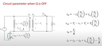
I'm starting with flyback converter theory. In continuous mode I understand from web that when energy is transferred to the second winding (off state) the secondary voltage (equal to load and capacitor voltage) is constant and current decreases. The energy from the transformer core recharges capacitor and supplies the load. How the capacitor can be charged if voltage is constant? How does capacitor voltage change during off state?
Thank you
 

Solution
Energy in the Tx = 0.5 B^2 Ae. Lg / Uo. Ur, for a ferrite with an air gap most of the energy is stored in the gap, so Ur = 1, and Lg = length of gap

The voltage on the cap is not constant, at fet turn off the current rises in the sec side coil ( how fast it rises depends on a number of factors including the flyback volts on the pri and the leakage inductance pri to sec ) the current is quite high to start with and ramps linearly down wards until the mosfet is turned on again.

So if you can see the cap volts clearly, there will be an ESL/ESR jump as the current jumps up to its max value, on top of this the cap voltage will rise at a falling rate .... - for a large cap this rise may be only a few 10's or 100's of mV.
 
Solution
dVc /dT = Ic / C. where Ic = Iave in the cap over the discharge time of the Tx ( current in the sec wdg ) minus the drop in V due to any load currents
 

Here is an LTspice sim of flyback so you can change ESL and ESR etc, and see how it works.
LTspice is free download
 

Attachments

  • Flyback _CCM.zip
    1.6 KB · Views: 46
Energy in the Tx = 0.5 B^2 Ae. Lg / Uo. Ur, for a ferrite with an air gap most of the energy is stored in the gap, so Ur = 1, and Lg = length of gap

The voltage on the cap is not constant, at fet turn off the current rises in the sec side coil ( how fast it rises depends on a number of factors including the flyback volts on the pri and the leakage inductance pri to sec ) the current is quite high to start with and ramps linearly down wards until the mosfet is turned on again.

So if you can see the cap volts clearly, there will be an ESL/ESR jump as the current jumps up to its max value, on top of this the cap voltage will rise at a falling rate .... - for a large cap this rise may be only a few 10's or 100's of mV.
Thank you for your quick reply. It s clear for me.
 

Energy in the Tx = 0.5 B^2 Ae. Lg / Uo. Ur, for a ferrite with an air gap most of the energy is stored in the gap, so Ur = 1, and Lg = length of gap

The voltage on the cap is not constant, at fet turn off the current rises in the sec side coil ( how fast it rises depends on a number of factors including the flyback volts on the pri and the leakage inductance pri to sec ) the current is quite high to start with and ramps linearly down wards until the mosfet is turned on again.

So if you can see the cap volts clearly, there will be an ESL/ESR jump as the current jumps up to its max value, on top of this the cap voltage will rise at a falling rate .... - for a large cap this rise may be only a few 10's or 100's of mV.
Thank you for your reply. as you say, the current ramps linearly down wards until the mosfet is turned on again and the cap voltage will rise at a falling rate. But what I find often on the web is a classic schematic with a diode, capacitor and resistance on secondary. When the switch is off current in secondary winding decreases linearly but the voltage is proportional to Vg (generator) and so constant. It means that cap voltage must be constant too. Maybe there are factors I'm not taking into account, but for the current in capacitor I=Cdv/dt so if current ramps down Vc can't be constant, I think.
 

Hi,

in a flyback SMPS there is the L that charges the capacitor.

but I think you missed that there needs to be a load current that discharges the capacitor.

(average of charging current) = (average of load current)

Klaus
 

Hi,

in a flyback SMPS there is the L that charges the capacitor.

but I think you missed that there needs to be a load current that discharges the capacitor.

(average of charging current) = (average of load current)

Klaus
Yes in on state a load current discharges the capacitor but in off state current from L charges capacitor and supplies power to the load. What is not clear for me is why in off state L current (Id) decreases and V2=Vc=Vo is constant (or not?)
 

Attachments

  • Flyback.JPG
    Flyback.JPG
    61.3 KB · Views: 78

Status
Not open for further replies.

Similar threads

Part and Inventory Search

Welcome to EDABoard.com

Sponsor

Back
Top