88sanz
Newbie level 5
Hi,
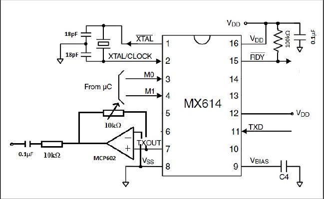
I've designed a modulator using MX614P for my project of satellite communication (CubeSat). A COTS ALINCO DJ-S45E transceiver was used to transmit data received from the modulator.
However, when I connect the transceiver to my modulator, it would cause fluctuation in the power supply for my modulator. I would like to ask what would be the cause for this situation and how to resolve it?
Thanks in advance.
") there are several possibilities for the voltage fluctuations.
there are several possibilities for the voltage fluctuations.
