Kolmjalg
Newbie level 1
Hi all,
I'm bit of stuck here with a power circuitry design of a specific ASIC. I need a reasonable/elegant solution for implementing new 'Vdd / 2' tied power rails for a sub-circuit.
Another words ASIC is designed to operate with +2.4 .. +3.0 V and sub-circuit should get its new power rails of (Vdd / 2) - 1V and (Vdd / 2) + 1V. (ie. in case of Vdd=2.4V, rails are 0.2V and 2.2V, in case of Vdd=3.0V, rails are 0.5V and 2.5V).
Technology is 0.5µm and first priority is low power consumtion.
My first idea was based on following circuit (self-drawn, Cadence plots are left in university).
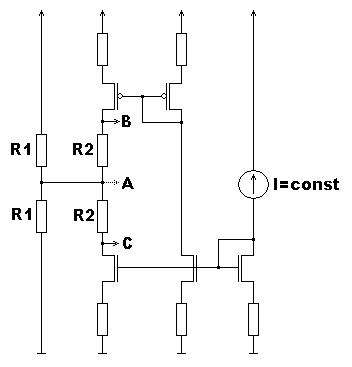
[ here A -> Vdd / 2; B -> Vdd / 2 + 1V; C -> Vdd / 2 - 1V ]
Resistors R1 give Vdd / 2 and resistors R2 raise and lower ths exact ±1V from mirrored current... BUT... problem stands in constant current source design. Right now I can't think of a way to simply form constant current in Vdd range +2.4 .. +3.0 V.
I'm bit of stuck here with a power circuitry design of a specific ASIC. I need a reasonable/elegant solution for implementing new 'Vdd / 2' tied power rails for a sub-circuit.
Another words ASIC is designed to operate with +2.4 .. +3.0 V and sub-circuit should get its new power rails of (Vdd / 2) - 1V and (Vdd / 2) + 1V. (ie. in case of Vdd=2.4V, rails are 0.2V and 2.2V, in case of Vdd=3.0V, rails are 0.5V and 2.5V).
Technology is 0.5µm and first priority is low power consumtion.
My first idea was based on following circuit (self-drawn, Cadence plots are left in university).
[ here A -> Vdd / 2; B -> Vdd / 2 + 1V; C -> Vdd / 2 - 1V ]
Resistors R1 give Vdd / 2 and resistors R2 raise and lower ths exact ±1V from mirrored current... BUT... problem stands in constant current source design. Right now I can't think of a way to simply form constant current in Vdd range +2.4 .. +3.0 V.