saad
Advanced Member level 4
Hello everyone,
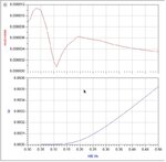
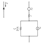
I am trying to simulate the noise of a Schottky diode power detector. Theoretically, the flicker noise should approach zero if there is no dc bias but the simulation results I am getting using ADS are quite the contrary. Any comments and experiences are welcome.
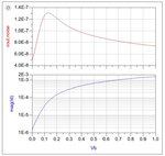
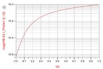
PS: I am attaching the plot of Id and output noise vs the DC bias voltage.
I am trying to simulate the noise of a Schottky diode power detector. Theoretically, the flicker noise should approach zero if there is no dc bias but the simulation results I am getting using ADS are quite the contrary. Any comments and experiences are welcome.
PS: I am attaching the plot of Id and output noise vs the DC bias voltage.

") Thanks a ton.
Thanks a ton.