Continue to Site

Welcome to EDAboard.com

Welcome to our site! EDAboard.com is an international Electronics Discussion Forum focused on EDA software, circuits, schematics, books, theory, papers, asic, pld, 8051, DSP, Network, RF, Analog Design, PCB, Service Manuals... and a whole lot more! To participate you need to register. Registration is free. Click here to register now.

FIR filter for DAC in STM32

Status
Not open for further replies.

yefj

Advanced Member level 4
Joined
Sep 12, 2019
Messages
1,175
Helped
1
Reputation
2
Reaction score
3
Trophy points
38
Activity points
7,063
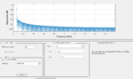
Hello, I have used matlab to create a filter with response as shown bellow.
using matlab i created the attached file with the coefficients
csvwrite('FilterCoef.txt',Num)

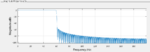
i have created a stepped response as shown bellow,after that i am olanning to connect the DAC output to ADC input.
then i have an array of a samples and i do a convolution between the sampled array and the filter array.
two question are rising afterwards:
how many ADC samples do i need for the convoltion to do correct filterring?
How then i present the filtered data?(sending it again to DAC?)
Thanks.
1614358086549.png
1614353788779.png

1614358477779.png
 

Attachments

  • 1614353448532.png
    1614353448532.png
    93.6 KB · Views: 130
  • 1614357964801.png
    1614357964801.png
    59.4 KB · Views: 125

Hi,

* How many samples:
It depends what you want to achieve. Often used: The period time iof the lowest frequency you want process, or as many samples as your FIR filter has taps.
* Where to present the data:
If you don't know what to do with the data ... how can we know?

You don't tell sampling frequency, signal input, application, what you want it to do....
All we can do is guessing. Is it a riddle?

Klaus
 

Hello Klauss ,its not a riddle :)
my ADC is 36Mhz clock VDDA=3.6V 12 bit resolution.
I have 661 coefficients for the filter.
so i need 661 samples?
my goal is to see the filtered response which supposed to be sinus on the scope.
SO i put theconvolution result samples as DAC DMA?
 

How does 36 MHz ADC sampling rate fit the filter sampling rate of about 4 kHz? Can you please clarify the intended system topology?
 

Hi,

ADC clock and sampling rate often differ. Sampling rate is of interest.
What's the sine frequency?

The filter seems to be a rather narrow bandpass. If so: What's it's center frequency?

If you want to see it on a scope
... the FIR filter output is digital
... you need an analog signal
So you need a digital to analog conversion. DAC.

DMA or not won't have influence on digital values, nor analog values. It usually reduces processing time and relaxes timings.
Thus it's a good idea to use DMA.
DMA or not in detail depends on microcontroller, interface, ADC, libraries, your programming effort ....

Klaus
 

I presume you are referring to STM32F407 as in your previous thread collection. 36 MHz is in fact maximal ADC clock frequency, maximal sampling rate is a few MHz, feasible only as DMA burst rate but not as continuous throughput.
--- Updated ---

Are you designing real time signal processing or only replaying a small prerecorded signal sample out of memory? In the former case, the FIR filter processing time restricts the achievable continuous data rate in the first place.
 
Last edited:

Your part does -

1614427504746.png


Your DAC even slower, you would have to decimate filter out stream -

1614427780619.png


Note that max sample rate much worse for larger scale transition, 100 Khz for a full scale
transition.


Regards, Dana.
 

Hello I have defined DAC1 using APB1 21MHZ clock as shown in the diagram bellow.
Then i defined ADC in IN6 which is located on APB2 its CLK is 84MHz after prescaler=4 we get 21MHz,
ADC parameter setting is as bellow but ihave a logical problem
i can generate a squared waveform in the while(1) loop.
But how do i keep sample this signal?
its a sequential code,how generate code from DAC and sample it simultaniosly?
Thanks.
1614871947344.png

1614870346029.png

1614872427493.png
 

Hi,

That's why the microcontrollers have a lot of features.
Generally I think it's not a good idea to use 100% processing power to generate a PWM.
* the better method is to use an interrupt and generate a PWM with maybe less than 1% processing power
* or even better: use the hardware timer counter periferal and generate a precise, jitter free PWM without (zero) processing power

And the same applies to the ADCs and DACs. The sampling timing can be controlled by a (another, but maybe even the same) timer.
No processing power for this.
Then you may fetch the data sample by sample with interrupt an ISR ...
Or better: use the DMA, it may sample and store a lot if samples without processing power.
Then you have plenty of time and processing power left to process the data...while at the same time the PWM runs and the ADCs and DACs.

Read datasheets, read application notes, go through example circuits.
It's all available for free. Nothing special..

Klaus
 

Hello Klauss,I was able to generate a signal using DAC periphery and a HAL_DELAY. I want to sample this signal using ADC by connecting DAC output to ADC input for FIR filter purposes. But because the code is sequential after generating DAC commands value I can sample with ADC commands but there will be only one DAC value to sample.

How PWM solves this logical problem.
I read something about pinpong two ADC to do such a thing but icant imagine how it works so it i will be able to generate a signal and sample it simulteniosly.
Thanks.
 

Hi,

HAL delay is not the way to go. It consumes all processing power and in case you want to process something you cause the sampling frequency to jitter and to get unprecise.
I think I never used this or similar method in the past 30 years...

In an project we do:
* 8 ch ADC sampling, continously and precise, 8 channels FIR filtering, storing, and displaying
* 115kbaud full duplex communication on one UART with PC
* 1MBaud sensor bus on another UART
* slow bus on a third UART communiating with several devices
* continously communicating with PLD, 3 IO extenders, 2 Flash memories, RTC, NVRam, display via one SPI bus
* software clock, a control loop, runing every 10ms, other jobs every ms
* calculations, plausibility checks,
Mind: all at the same time, not missing a single bit at each bus or ADC...
On an STM32F107, 72MHz
All this with just 5% processing power! 95% of time the microcontroller is in sleep mode to save power.

There's no need for you to do the same. I just want to give you an idea how powerful nowadays microcontrollers are....when you use the features.

Klaus
 

Just for future reference there are parts out there quite easy to use that
accomplish a signal path like you are trying to implement. Here is an
example project....

About 20 lines of code, operates in background, can use its 12 bit SAR vs 20 bit
DelSig shown. FIR to 128 taps, BiQuad cascades......

Single chip, see right hand window, most resources not used, can be used for other tasks.

1614900151798.png


1614900282049.png


Regards, Dana.
 
  • Like
Reactions: yefj

    yefj

    Points: 2
    Helpful Answer Positive Rating
Hello Klauss,Yes i will use timer interrupt based delay instead of HAL_DELAY.
I got a recipe
ADC(DMA)->buffer1/2->(callback) FIR processing->buffer->DAC(DMA)
What is the meaning of buffer 1/2?
what is the meaning of callback FIR?
a callback i know from matlab is a function that being called on some occation.
i am having problem to imagine how this callback FIR is working.
THanks.
 
Last edited:

Hi,
i will use timer interrupt based delay
I don't like the word "delay" in this case. Just be sure it does no "busy wait" for an interrupt.
Why no direct hardware control the sampling rate?
There's nothing against interrupt ... when doing it correctly. In doubt show your code or flow chart (don't say you don't have one).

Klaus
 

Hello ,I just want to see the effect of FIR or IIR on a noisy signal.
I tried my best to look for the simplest manual to see the effect but i codnt.
Could you please reccomend me some very good newbie manual?
Thanks.
 

Sim it -


In PSOC Creator you can use the PRS module to generate a random signal and one of the DACs
to feed the filter to check out signal path. PRS module is Psuedo Random Sequence generator.
That again is single chip, eg, the filter, A/D two DACs, DMA, PRS, Vref, OpAmp.....


Regards, Dana.
 
Last edited:

I presume, the problem isn't FIR filter design as such, it's implementation in microcontrollers.
 
  • Like
Reactions: yefj

    yefj

    Points: 2
    Helpful Answer Positive Rating

Status
Not open for further replies.

Similar threads

Part and Inventory Search

Welcome to EDABoard.com

Sponsor

Back
Top