Continue to Site

Welcome to EDAboard.com

Welcome to our site! EDAboard.com is an international Electronics Discussion Forum focused on EDA software, circuits, schematics, books, theory, papers, asic, pld, 8051, DSP, Network, RF, Analog Design, PCB, Service Manuals... and a whole lot more! To participate you need to register. Registration is free. Click here to register now.

[SOLVED] Find Pulse Width in Simulink

Status
Not open for further replies.

Shachar85

Member level 2
Joined
Jan 25, 2011
Messages
43
Helped
0
Reputation
0
Reaction score
0
Trophy points
1,286
Activity points
1,638
Hello

I'm trying to find the duration of a pulse of an incoming PWM. I'm using Simulink for that.

First I tried to use a counter to count microseconds between rising and falling trigger.

It worked great on simulation, but when I tried it on external mode (as I need this model to be),
the sample time just killed the model and the time of the model increased very slowly (0.001 seconds in the model for 1 second in reality).


Can anyone think of a way to measure pulse width? (or duty cycle)

Thank you
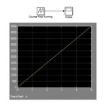
 

Where is your signal come from?
 

Eventually, the signal is supposed to come from a receiver, as a PWM signal, and enter the Arduino microcontroller.

But the problem happens before getting any signal from the real world.
I attached an image of a very simple model. While in simulation mode, it works very fast, of course.
If I run the same model on external mode (Arduino is connected), and counter's sample time is 0.0001 [sec], it takes about 20-30 seconds to finish a 5 seconds run.

So the real time and simulink time is not synchronized. You can guess that it can cause a problem for sampling a PWM signal


Exa.jpg
 

Simulink is not suitable for real-time applications. So you need m-code, or if you want an online visualization you should use GUI.
 

Could you please explain what you mean - simulink is not suitable for real-time?
I mean - It has an external mode. It has blocks specific to Arduino (and other microcontrollers as well)

My whole project is based on simulink, so it is very important to me. Please explain
 

I dont know what to say but a lot of developers over the world meet the timing problem like you do.
So do me when working with COM-port.
So to write the m-script is my advise.
 
Those are some bad new...
But it's better to know now than later.

One last question about it - Is it possible to write a m-script and put it as a block in simulink?
I want to know if I can still work, partly, with simulink
 

I'm not sure but I think m-script or any level S-function execution will be based on model sample times which do not correspond to real time.
 

Well, I thought of another idea. LPF to convert the PWM to analog voltage and then sample the analog voltage in simulink.


Thank you for your answers
 

Status
Not open for further replies.

Similar threads

Part and Inventory Search

Welcome to EDABoard.com

Sponsor

Back
Top